 15 May, 2026
 Industry News Industrial Use
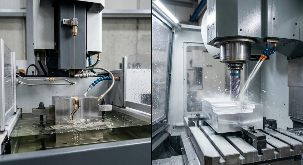
Wire EDM beats milling when you need to cut hardened metal, sharp internal corners, or thin fragile features without applying any cutting force — milling wins on almost everything else because it’s faster and cheaper per part. The real decision isn’t “which process is better,” it’s “which one actually respects the geometry and material you designed.”
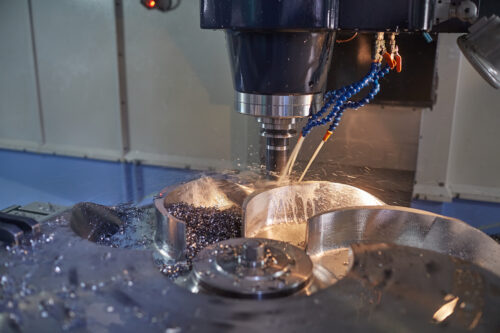
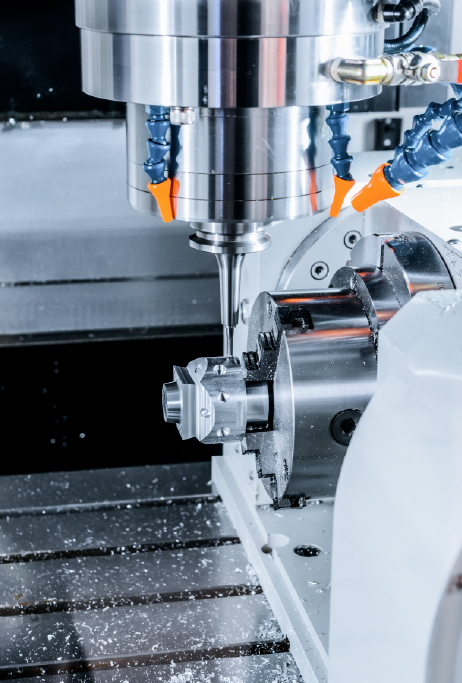
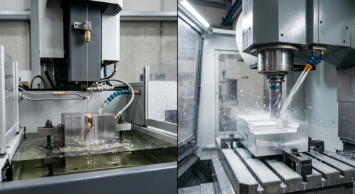
Milling removes material by pushing a rotating cutter into stock. That means cutting forces, vibration, and heat — all of which can deflect a part, especially if it’s thin, tall, or unsupported. Wire EDM removes material with electrical discharges between a thin brass or coated wire and the workpiece, submerged in dielectric fluid. No contact, no cutting force, no tool deflection.
That single difference explains almost every scenario where EDM outperforms milling. If your part can tolerate a little cutter pressure, milling is almost always the smarter economic choice. If it can’t — because it’s 0.3 mm thick, hardened to 60 HRC, or has a slot with a corner radius smaller than any standard end mill — EDM takes over.
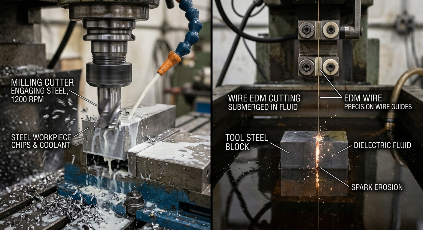
There are geometries and materials where milling isn’t a competitive option at all, not just a costlier one.
Once steel is heat-treated past roughly 50-55 HRC, milling tool life drops fast and surface quality suffers. EDM doesn’t care about hardness — it erodes material by spark discharge, so a die insert hardened to 62 HRC cuts about as predictably as mild steel. This is why stamping dies, punches, and mold cavities are frequently finished with EDM after heat treatment rather than before.
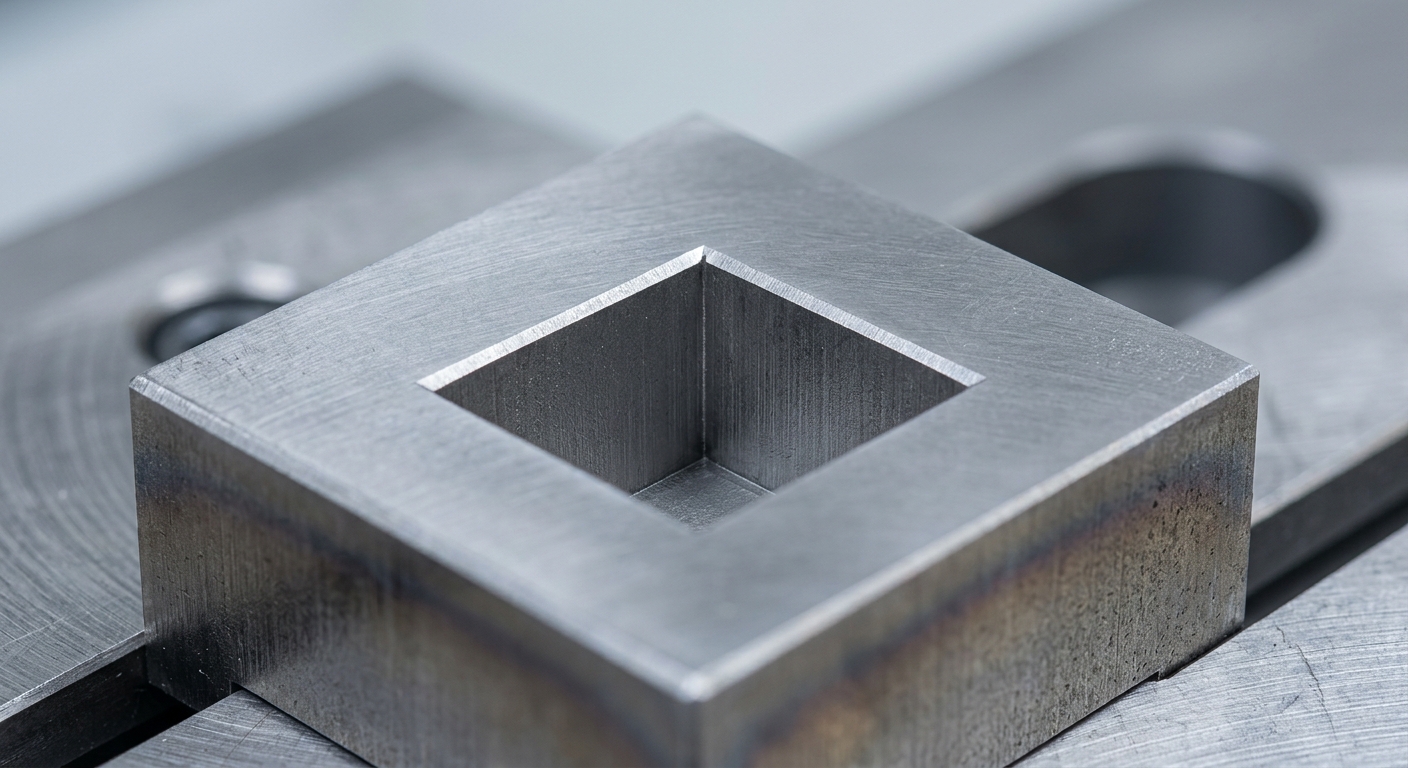
A milling cutter is round. Every internal corner it produces has a radius equal to or larger than the tool radius — there’s no way around this with a rotating tool. Wire EDM cuts along a programmed path with a wire as thin as 0.1-0.3 mm, so internal corners can be nearly square. If your drawing calls out a sharp internal corner with no fillet allowed, that’s a strong signal the feature needs EDM, not milling.
Milling a 0.5 mm wall is a fight against chatter and deflection. EDM doesn’t push on the part, so it can cut delicate comb structures, thin fins, or narrow slots that would flex or snap under a cutting tool.
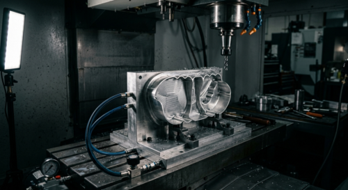
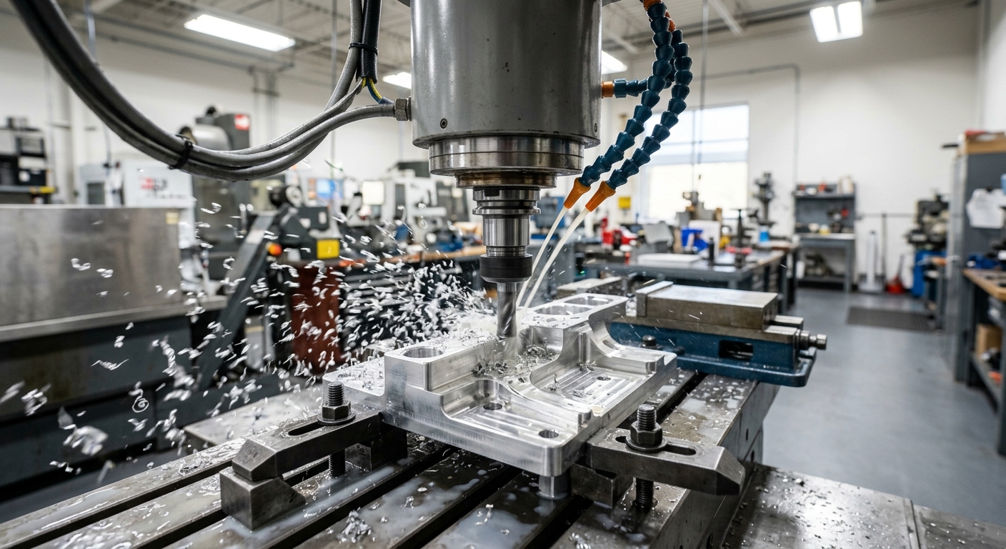
Milling isn’t the fallback option — for most parts it’s simply the right tool. Three-axis and 5-axis CNC machining remove bulk material fast, handle complex 3D contours, and machine features like pockets, bosses, holes, and threads in a single setup.
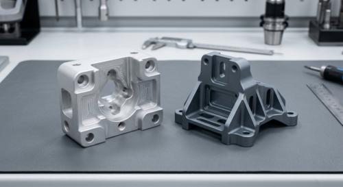
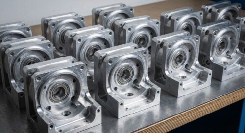
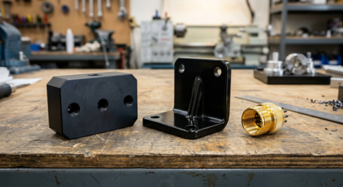
Think about a typical aluminum enclosure or bracket. It needs mounting holes, a pocketed cavity, chamfered edges, and a flat mating face. Milling handles all of that in one program run. Wire EDM can’t drill a hole efficiently, can’t cut a 3D contoured surface, and struggles with anything that isn’t a through-cut or 2D profile. For general-purpose parts — brackets, flanges, housings, shafts turned on a lathe — milling and turning remain the default, and rightly so.
Cost matters too. EDM pricing is driven largely by cut length and material thickness, since the wire has to travel the entire profile at a controlled feed rate. Milling removes material in bulk, so for parts with a lot of open pocketing and less intricate detail, it’s almost always cheaper per unit.
Consider a manufacturer of automotive stamping tooling. The die insert is made from D2 tool steel, heat-treated to around 58-60 HRC for wear resistance, with a profile that includes a sharp internal notch to match a stamped bracket geometry. Milling this after hardening would chew through carbide end mills and still leave a rounded corner where the drawing needs a near-sharp edge.
The practical approach: rough the shape in the soft state with milling to remove bulk material efficiently, heat-treat the insert, then finish the profile and the sharp notch with wire EDM. This sequence uses each process where it’s strongest — milling for fast material removal, EDM for hardness-independent precision on the finished geometry. It’s a pattern seen constantly in mold and die shops, and it’s worth asking your supplier whether a similar rough-then-EDM sequence applies to your hardened components.
Wire EDM has a reputation for extreme precision, and it’s earned — wire path accuracy can reach ±0.002-0.005 mm on well-controlled setups, though achievable results depend on wire diameter, material thickness, and machine condition. But precision on the wire path isn’t the same as precision on the finished part. EDM leaves a thin recast layer — a heat-affected zone from the discharge process — that may need to be removed for fatigue-critical or medical applications.
Milling tolerances of ±0.01-0.05 mm are typical for general work, and tighter tolerances are achievable with rigid fixturing, sharp tooling, and appropriate feeds. For a deeper breakdown of how tolerance choices affect cost and process selection, see Understanding Tolerances: How Precise Does Your Part Really Need to Be. Neither process guarantees a specific number without knowing material, geometry, and inspection method — treat any tolerance claim as application-dependent until it’s been reviewed against your actual drawing.
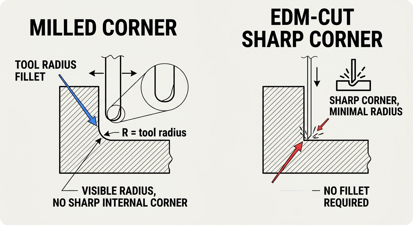
It’s rarely an either/or decision on complex tooling and precision components. A common workflow: mill the bulk geometry, drill and tap holes, then use wire EDM only for the specific features that milling can’t produce — a keyway with a sharp corner, a thin slot, a hardened insert profile. This hybrid approach controls cost by letting EDM handle only what it must.
Medical device components are a good example. A surgical instrument housing might be milled from stainless steel for its overall shape and mounting features, then have a narrow slot cut by EDM where a spring-loaded mechanism needs a precise, burr-free channel that a small end mill couldn’t reach without excessive tool deflection.
EDM lead times and costs scale with cut path length and material thickness — a thick tool steel block with a long intricate profile takes considerably longer to wire through than the same profile in a thin sheet. Milling costs scale more with material removal volume, number of setups, and tool changes.
For prototyping, milling is usually the faster route to a functional part unless the design specifically requires EDM-only features. For low-volume production of tooling components, EDM’s cost per part often improves relative to milling because there’s no tool wear penalty on hardened material — a carbide end mill wears out; a wire doesn’t care how hard the steel is.
| Factor | Wire EDM | CNC Milling |
|---|---|---|
| Material hardness limit | None (conductive materials) | Practical limit ~45-50 HRC |
| Sharp internal corners | Yes | No — tool radius always present |
| Cutting force on part | None | Present, can cause deflection |
| Best for | Dies, thin slots, hardened inserts | Brackets, housings, general 3D parts |
| Cost driver | Cut length & thickness | Material removal volume |
Before locking in a process on your RFQ, run through a short checklist:
Reviewing your drawing against these questions before quoting saves back-and-forth later. For general cost-reduction strategies applicable to milled parts, see Design for CNC Machining: 10 Tips to Reduce Cost.