
CNC Machining Guide for Engineers: Processes, Materials, Tolerances and Cost
-
 12 Aug, 2026
-
 Industry News Machining Basics
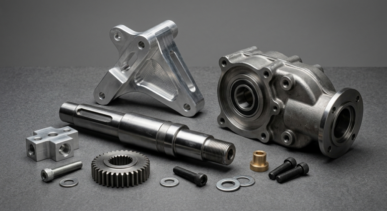
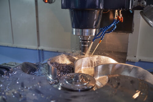
CNC machining is the process of removing material from a solid block or bar using computer-controlled cutting tools to produce precision metal or plastic parts, and the right choice among milling, turning, and 5-axis machining depends almost entirely on part geometry, not preference. Materials and tolerances then dictate cost far more than most engineers expect — tightening a tolerance from ±0.1 mm to ±0.02 mm can double machining time on the same part. This guide walks through the practical decisions that actually move the needle on quality and price.
Milling, Turning, or 5-Axis? Match the Process to the Geometry
Here’s a mistake we see constantly: engineers specify 5-axis machining for a part that a 3-axis mill could handle in half the time. The process should follow the geometry, not the other way around.
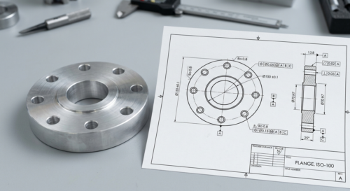
CNC turning is the right call for rotationally symmetric parts — shafts, pins, bushings, flanged fittings. A lathe holds concentricity and roundness better than milling ever will, and cycle times are fast because the part spins continuously against a fixed tool.
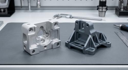
3-axis milling handles prismatic parts well — brackets, plates, housings with features accessible from a few directions. It’s the workhorse process because tooling is simple and setup is fast.
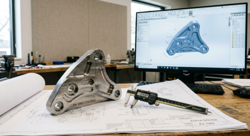
5-axis machining earns its higher cost when a part has compound angles, undercuts, or features that would otherwise require multiple setups and re-fixturing. A turbine bracket with angled mounting faces on three sides might need six separate 3-axis setups — or one 5-axis setup. That’s exactly why aerospace companies rely on multi-axis machining for structural components with complex load paths.
Where Wire EDM Fits In
Wire EDM isn’t a milling alternative — it’s a specialist tool for geometry that cutting tools physically can’t reach: sharp internal corners, thin slots in hardened tool steel, or intricate profiles in materials too hard to mill economically. If your part needs a 0.1 mm internal radius in hardened D2 steel, EDM is the answer, not a smaller end mill.
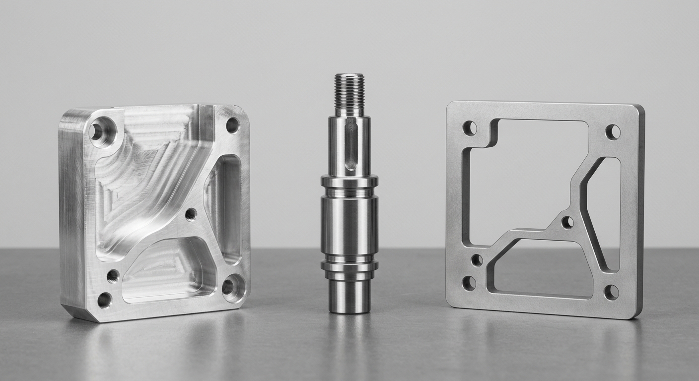
Choosing Materials: What Actually Changes the Machining Outcome
Material choice affects three things simultaneously: how the part performs in service, how fast it can be cut, and how much tool wear the shop absorbs. Engineers who pick materials purely on mechanical properties often get a cost surprise later.
Aluminum 6061 is the default for a reason — it machines fast, holds decent tolerances, and is forgiving of aggressive feeds. 7075 offers roughly 40% higher tensile strength but machines less predictably and costs more per pound; the trade-offs are covered in detail in Aluminum 6061 vs 7075: Strength, Cost, and Machinability.
Stainless steels bring their own headaches — work hardening, heat buildup, and gummy chip formation if feeds and speeds aren’t dialed in correctly. If your part is 304 or 316, review tips for machining stainless steel with better surface quality before finalizing geometry, especially for thin-wall sections.
Engineering plastics — POM, PEEK, Delrin, nylon — behave nothing like metals under a cutting tool. They deflect, they heat up locally, and some (like PEEK) are notoriously prone to warping if internal stresses aren’t relieved. See the best plastics for CNC machining for a breakdown by application. Full material data and grade comparisons are also available on the materials page.
A Quick Real-World Example
A robotics startup once specified 7075 aluminum for a lightweight gripper housing purely for strength margin, without checking whether 6061 would meet the actual load case. Switching to 6061 after a stress analysis cut machining time by roughly 20% and dropped material cost — with no measurable performance loss in the application.
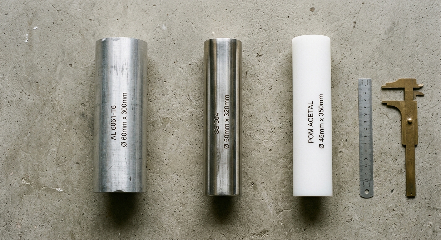
Setting Tolerances That Match the Function, Not the Fear
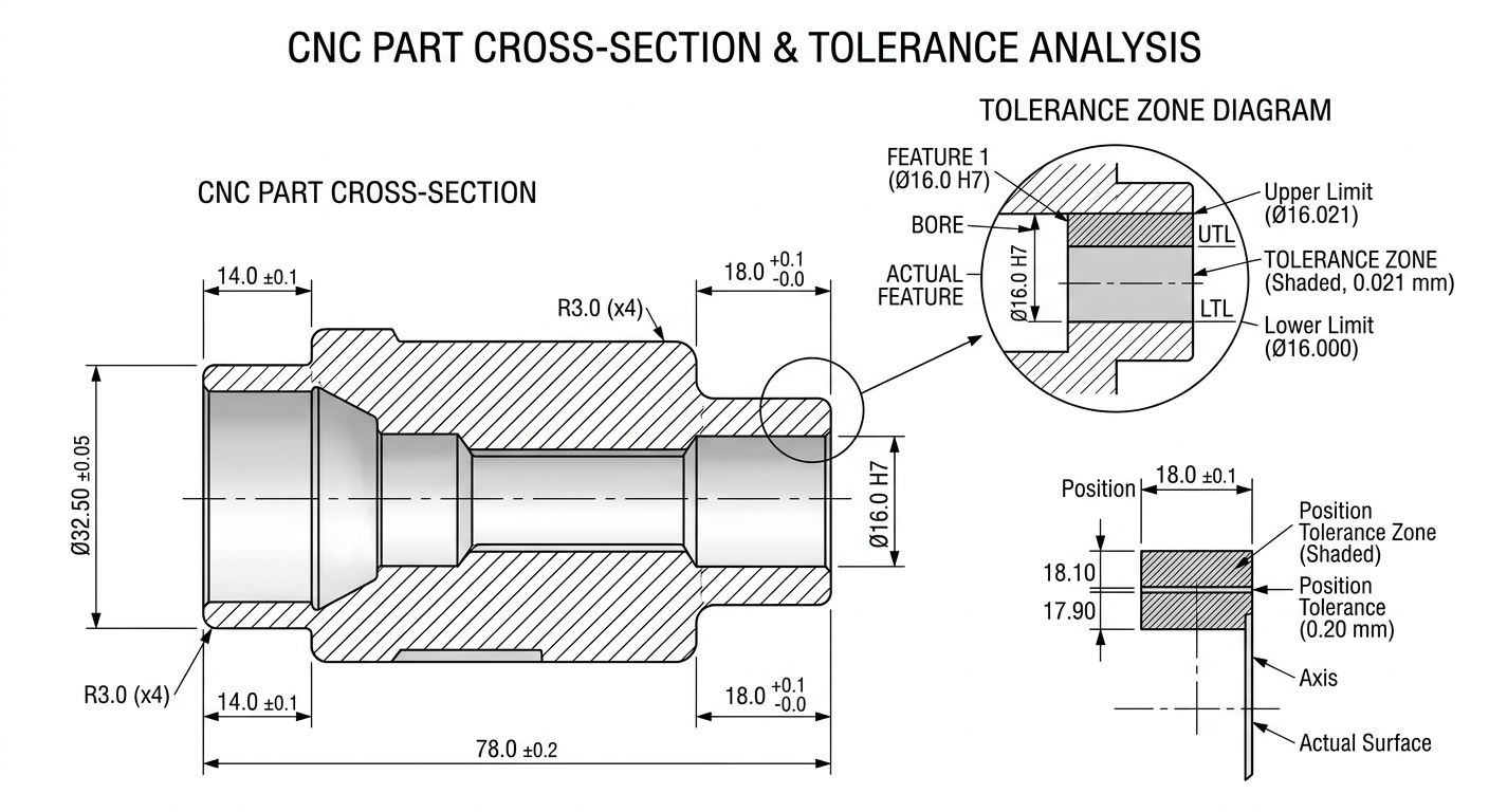
Over-specifying tolerances is one of the most expensive habits in mechanical design, and it’s completely avoidable. A tolerance of ±0.1 mm is achievable on almost any 3-axis mill with standard tooling. Push that to ±0.02 mm and you’re now talking about slower feeds, more inspection time, temperature-controlled measurement, and sometimes a different machine altogether.
The rule of thumb: tolerance the features that actually need it — bearing bores, mating faces, pin locations — and leave everything else at a general tolerance band. A bracket with twelve dimensions doesn’t need all twelve held to ±0.02 mm just because two mounting holes do.
GD&T callouts should reflect functional requirements, not habit. Flatness matters on a sealing face; it rarely matters on a non-mating edge. For a deeper walkthrough of how to decide what precision your part actually needs, see Understanding Tolerances: How Precise Does Your Part Really Need to Be?
Tolerance Stack-Up Is the Silent Killer
Individual tolerances that look reasonable in isolation can stack into an assembly problem. Four mating parts each toleranced at ±0.05 mm can add up to a ±0.2 mm worst-case gap — enough to cause interference or excessive play in a precision fixture. Always check the assembly tolerance chain, not just the individual part drawing.
Surface Finish: The Cost Driver Nobody Budgets For
A machined surface straight off the mill is typically Ra 1.6–3.2 µm — perfectly fine for internal structural parts. But if a drawing calls out anodizing, bead blasting, or a mirror polish, that’s an additional process, an additional lead-time step, and an additional cost line that often gets overlooked in early quoting.
Some finishing choices also change dimensions. Anodizing adds a few microns of oxide layer; electroless nickel plating adds measurable thickness that has to be accounted for in the pre-finish machining tolerance. Skipping that adjustment is a common reason plated parts fail final inspection. Review finishing options and their trade-offs on the surface finishing page before locking in a spec.
Match Finish to Function
- Bead blasting — cosmetic uniformity, doesn’t add dimensional thickness
- Anodizing (Type II/III) — corrosion resistance and color, adds minor thickness
- Electroless nickel — wear resistance, adds measurable plating thickness
- Passivation — corrosion resistance for stainless, no dimensional change
What Actually Drives CNC Machining Cost
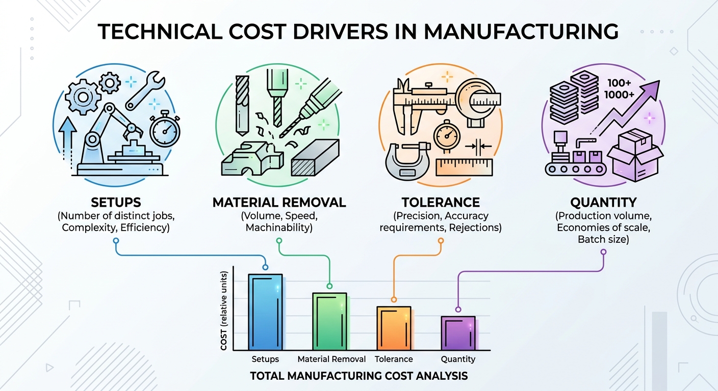
Cost isn’t really about the material price — it’s about machine time, setups, and tooling. Four variables control most of the quote:
1. Number of Setups
Every time a part needs to be flipped and re-fixtured, you’re adding labor time and introducing potential alignment error. A part designed to be machined in one or two setups is inherently cheaper than one needing five.
2. Material Removal Rate
Deep pockets, thin walls, and hard materials all slow down cutting speeds. A part that’s mostly stock with a few features machines faster than a part that’s 80% removed material.
3. Tolerance and Inspection Requirements
As covered above, tight tolerances mean slower cuts and more measurement time — sometimes CMM inspection with a full dimensional report instead of a quick caliper check.
4. Order Quantity
Programming and setup costs get amortized across the batch. A one-off prototype carries the full setup cost; a batch of 200 spreads that cost thin. For guidance on when a project should move from CNC prototypes to a different production method entirely, our team often reviews this during quoting — feel free to reach out through Contact Us for a project-specific breakdown.
Preparing a Drawing That Doesn’t Get Re-Quoted Three Times
A poorly prepared RFQ package is the number one cause of quoting delays. Suppliers can’t price ambiguity — if a critical dimension, thread spec, or finish requirement is missing, expect a round of clarification emails before you even see a number.
A solid RFQ package includes: a dimensioned drawing with GD&T where it matters, material and finish callouts, order quantity (including whether it’s a prototype or production intent), and any inspection or documentation requirements. For a full checklist of design decisions that reduce cost before the drawing even reaches a shop, see Design for CNC Machining: 10 Tips to Reduce Cost.
For example, an electronics OEM sourcing a heat sink housing sent a drawing with a general tolerance note but no callout on the flatness of the mating face against the PCB. The first batch came back within drawing spec but failed thermal contact testing — a flatness requirement that should have been specified up front. Getting the drawing review right the first time avoids exactly this kind of rework.
From Prototype to Production: What Changes
A prototype and a production part might share the same drawing, but they’re machined differently. Prototypes are typically run with general-purpose tooling and flexible fixturing because the priority is speed and design validation, not per-part cost. Production runs justify dedicated fixtures, optimized toolpaths, and sometimes different equipment entirely — which is why unit costs often drop significantly between a 5-piece prototype run and a 500-piece production order, independent of material cost.
Before scaling up, it’s worth revisiting whether CNC machining is still the right process at all. High-volume geometry that was fine for CNC prototyping sometimes makes more economic sense in die casting or injection molding once volumes climb — a break-even analysis that depends heavily on part geometry and annual volume. If you’re evaluating that transition, our capabilities page outlines the processes available for both low-volume and production-scale work.
Vetting a Supplier for CNC Work
Not every shop that owns a CNC mill can handle every job well. Tolerance capability, material experience, and inspection equipment vary widely between suppliers, and the difference often only shows up after parts arrive.
Before placing an order, it’s worth asking specific questions about equipment, quality documentation, and how the supplier handles first-article inspection or dimensional reports. We’ve laid out a full framework in Vetting a CNC Supplier: 12 Questions Before You Place an Order — it’s a useful checklist whether you’re placing your first order or switching suppliers after a quality issue.