 28 Jul, 2026
 Industry News Machining Basics
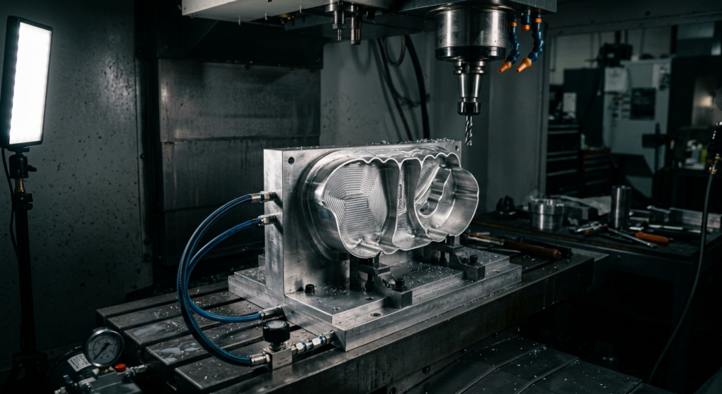
Thin-wall parts warp mostly because of how they’re held, not because the material is weak. Clamp a 0.030-inch wall the way you’d clamp a solid block, and you’re squeezing a structure that has almost no stiffness to resist the force — it deflects under the clamp, gets machined in that deflected shape, and springs back once released. The fix isn’t a better material or a slower feed rate. It’s rethinking the fixture so the part never gets pushed out of shape in the first place.
Here’s the thing people get wrong: warping on thin walls usually isn’t plastic deformation or thermal distortion — it’s elastic springback. The wall bends under clamping force, the cutter removes material while it’s bent, and when the clamp releases, the wall snaps back toward its natural shape. Except now there’s less material on one side than the other, so it doesn’t snap back straight. It bows.
A wall under 1mm thick can deflect measurably under as little as 20-30 lbs of clamping force, depending on geometry and support span. That’s not a lot. A standard vise or toggle clamp set for a solid aluminum block will absolutely blow past that number without anyone noticing, because the operator is thinking about workholding grip, not wall stiffness.
The part often measures fine on the machine, in the fixture. It’s only after unclamping — sometimes hours later, after the residual stress redistributes — that the bow shows up. That delay is exactly why this defect frustrates shops: everything looked good at the point of cut.
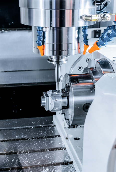
Even with a perfect fixture, an aggressive toolpath can flex a thin wall on its own. Radial cutting force pushes the wall away from the tool mid-cut, and if the wall isn’t backed up, it deflects, gets under-cut, then springs back after the tool passes — leaving a wavy, out-of-tolerance surface known as chatter-induced taper or wall bowing.
This is separate from clamping distortion but compounds it. A wall that’s already bent 0.002 inches from clamping, then flexed another 0.003 inches from cutting force, ends up with a combined error that’s hard to trace back to a single cause. For guidance on how tight tolerances actually need to be before you over-engineer the fixture, see Understanding Tolerances: How Precise Does Your Part Really Need to Be?
Switching from conventional to climb milling on the finish pass, and cutting the radial depth of cut in half, often does more to fix wall bowing than any fixture change. It’s a free fix that gets overlooked because it feels like a minor parameter tweak.
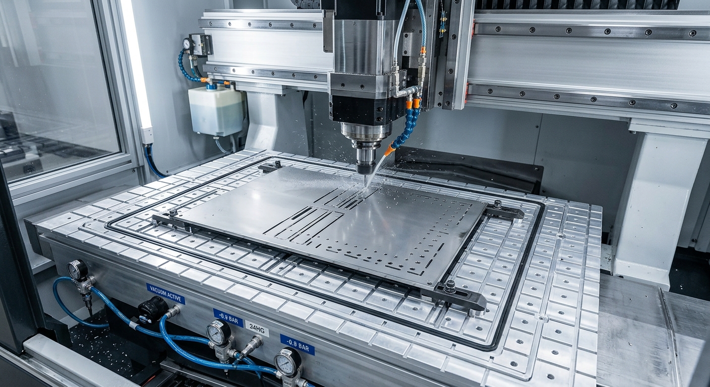
If the part is a flat or gently curved thin panel — a cover, a bracket face, a heat-sink plate — vacuum fixturing is usually the answer. Instead of point clamps squeezing from a few spots, vacuum applies distributed force across the entire back surface. No local high-stress zones, no springback pattern tied to clamp location.
A shop machining 0.5mm stainless steel EMI shield covers switched from mechanical clamps to a vacuum chuck and cut their reject rate from roughly 18% to under 3%. The parts weren’t redesigned. The material didn’t change. Only the way force was distributed changed.
Vacuum fixturing isn’t free, though — it requires a reasonably flat mating surface and a sealed table, and it won’t work well on parts with lots of through-holes unless you seal them individually or use a gasketed sub-plate.
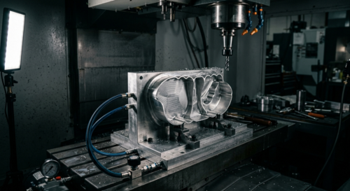
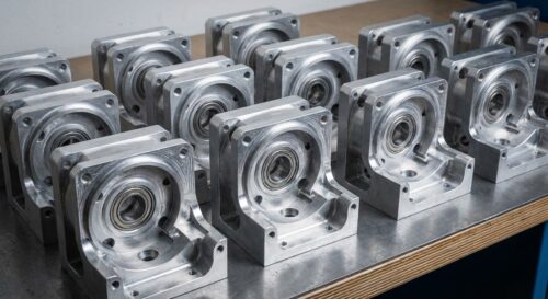
Not every thin-wall part is flat. Housings, brackets with ribs, and curved shells need support that matches their actual geometry — that’s where custom-machined soft jaws come in. Instead of gripping the part at two or three hard points, a soft jaw is bored or profiled to cradle the part’s exact outer contour, spreading contact force over a much larger area.
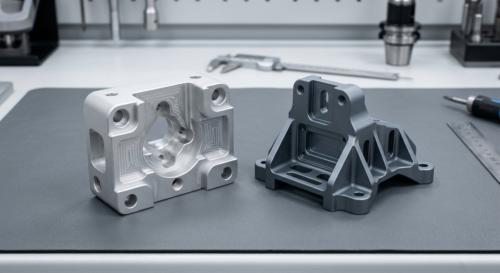
This matters most on parts that combine thin walls with thicker bosses or ribs — the soft jaw should contact the rigid sections, not the thin ones. Get the contact points wrong and you’re clamping directly on the weakest part of the structure, which is the worst possible spot.
Soft jaws take longer to machine than grabbing off-the-shelf jaws, but for a production run of more than a few dozen parts, the reject-rate savings pay for the setup fast. For one-off prototypes, this is often where teams lean on design-for-manufacturing adjustments instead — adding a temporary rib or tab that gets machined off later.
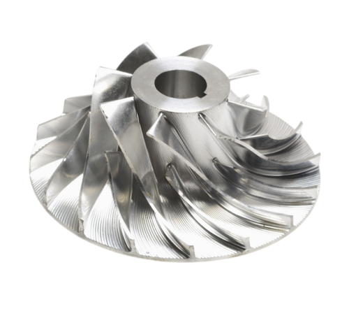
For genuinely fragile thin-wall geometry — think aerospace bracket webs under 0.5mm, or intricate medical device housings — sometimes the only reliable answer is embedding the part in a supporting medium before cutting. Low-melt wax, dissolvable adhesives, or eutectic alloys get poured or applied around the thin sections, filling every void so there’s nothing for the wall to flex into.
Once the wax hardens, the part is effectively a solid block for machining purposes. Cut, then melt or dissolve the wax away, and the thin walls come out exactly as machined — no memory of ever being unsupported.
This method is slower and adds a cleaning step, so it’s reserved for parts where the alternative is a high scrap rate. It shows up often in aerospace multi-axis work, where thin ribs and pocketed structures are common and scrap costs on exotic materials are painful.
Switching to a stiffer alloy buys you margin, but it doesn’t eliminate the mechanism. A thin wall in 7075 aluminum resists deflection better than the same wall in 6061, and stainless resists it better than aluminum in general — but push the wall thin enough and even titanium will bow under the wrong clamp. Material stiffness raises the failure threshold; it doesn’t remove the physics.
Plastics are the extreme case. Thin-wall nylon or POM parts have such low modulus that even hand-tight vises can distort them measurably. If you’re specifying plastic for a thin-wall design, it’s worth reading The Best Plastics for CNC Machining before locking in wall thickness, since some resins hold dimensional stability far better than others post-machining.
Stainless adds a wrinkle: it work-hardens as it’s cut and holds heat longer than aluminum, so thermal expansion during machining can mimic clamping-related warping. See Guide to Machining Stainless Steel for how that interacts with thin sections specifically.
One overlooked fixturing move — it’s not the fixture at all, it’s the toolpath order. If you rough out the thin-wall sections early in the program, the part loses its rigidity before the rest of the machining even starts, and every subsequent operation risks deflecting the now-floppy wall.
Better sequence: machine all the rigid features and reference surfaces first, keep the thin sections at near-full thickness as long as possible, and save the wall-thinning operations for last — ideally as a final light finishing pass with minimal clamping force. This alone has rescued plenty of designs that otherwise looked impossible to hold.
If you’re sourcing a thin-wall part, the conversation with your shop should happen before the first chip is cut, not after the first batch comes back warped. Flag which walls are thin, whether flatness or parallelism actually matters for the application, and whether the mating assembly can tolerate a small bow.
For instance, a customer designing a drone frame cover once assumed every wall needed 0.001-inch flatness because that’s what CAD defaulted to. Once the actual requirement — clearance for an internal battery, nothing more — was clarified, the shop switched to a cheaper vacuum-fixturing setup and dropped both cost and lead time. Check machining capabilities for the fixturing methods a shop already has on hand, since not every shop owns a vacuum table or soft-jaw setup.