 03 Aug, 2026
 Industry News Machining Basics
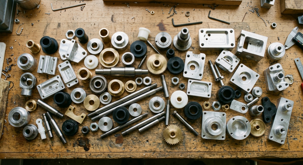
The short answer: if your part is round and symmetric around a central axis — think shafts, bushings, pins, fittings — turning is almost always faster and cheaper. If it’s got flat faces, pockets, slots, or off-axis holes, milling is the only way to get there. Most real parts actually need both, which is why so many shops quote mill-turn work by default rather than picking one process in isolation.
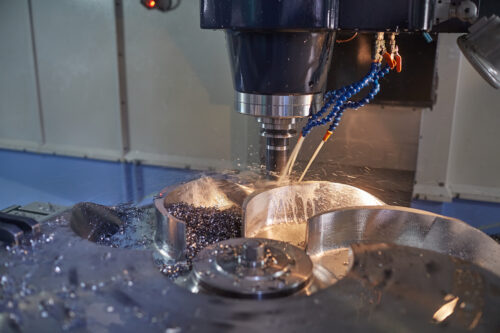
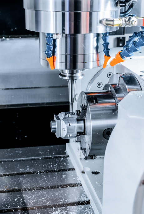
Here’s the mistake beginners make constantly: they think milling and turning are just “two ways to cut metal.” They’re not. The fundamental difference is what’s spinning. In turning, the raw stock chucks into a spindle and rotates at high speed while a stationary cutting tool moves in to shave material off — that’s how you get a perfectly round shaft in a single pass. In milling, the stock sits still (usually clamped to a table) and a rotating cutting tool moves around it in multiple axes to carve out pockets, slots, and contours.
That one distinction dictates almost everything downstream — achievable geometry, cycle time, tolerance stack-up, even which raw material shapes make sense (round bar for turning, plate or block stock for milling). Get this wrong on a quote request and you’ll either overpay for an unnecessarily complex setup or get a part that can’t physically be made the way you specified.
If your part is a cylinder, cone, or has any rotational symmetry, turning wins on cost almost every time. Why? Because a lathe removes material continuously as the part spins — there’s no repositioning, no tool-change-heavy pocketing, just one clean pass after another. A simple bushing that might take 8 minutes on a mill can often be turned in under 2.
Turning also naturally produces tighter roundness and concentricity than milling ever will, because the part’s own rotation defines the geometry. If your drawing calls for a tight bore-to-OD concentricity spec, don’t even consider milling it — you’ll fight the tolerance the whole way.
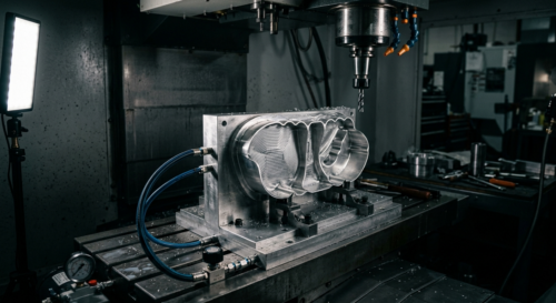
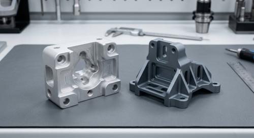
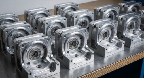
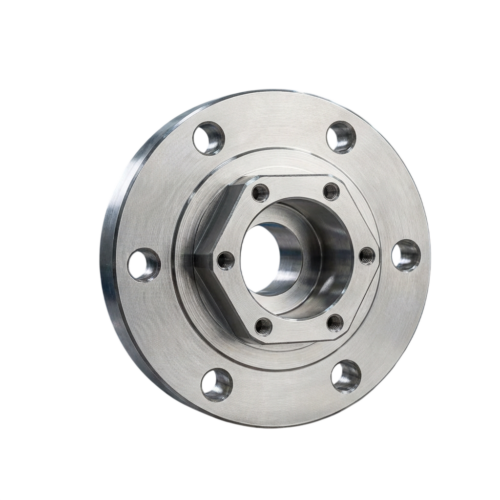
The moment your part has a flat face, an off-center hole, a pocket, or any feature that isn’t rotationally symmetric, turning is out and milling takes over. A mounting bracket with four corner holes and a stepped pocket? That’s a milling job, full stop — there’s no way to spin that geometry on a lathe.
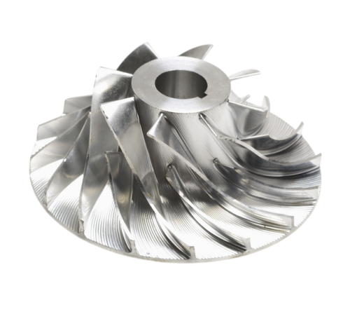
Milling’s real strength is flexibility. A 3-axis mill handles flat-face work fine, but once you need angled bosses, undercuts, or features on multiple sides without re-fixturing, you’re into 4-axis or 5-axis territory. We cover that decision separately in our piece on why aerospace companies rely on multi-axis machining, but the short version: more axes mean fewer setups, better accuracy, and less risk of stacking tolerance errors between operations.
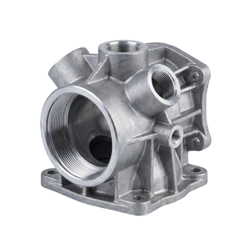
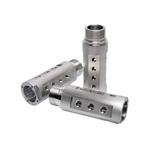
Take a hydraulic manifold fitting we see often — round body, threaded ports on the OD, but also two flat mounting tabs with drilled holes on opposite sides. A shop that only owns lathes will try to force the flats and holes with a rotary attachment and burn hours doing it badly. A shop that only mills will spend forever trying to hold roundness and thread concentricity on a 4-axis setup.
The right answer: turn the round body and threaded features first on a lathe, then move the part to a mill (or a mill-turn center) to add the flats and cross-holes. This is exactly the kind of part where combined turning and milling capabilities under one roof save real money — no shipping a part between two vendors, no re-fixturing tolerance loss.
People assume milling and turning hit similar tolerances. They don’t — not by default. A well-tuned lathe routinely holds ±0.0005 in on diameter because the cutting action is continuous and rigid. Milling, especially on thin walls or tall features, deals with tool deflection and vibration that make ±0.001–0.005 in a more realistic baseline without extra passes or fixturing tricks.
| Factor | CNC Milling | CNC Turning |
|---|---|---|
| Typical tolerance | ±0.001–0.005 in | ±0.0005–0.002 in |
| As-machined finish | 63–125 Ra | 16–32 Ra |
| Best geometry | Flat, angular, pocketed | Round, symmetric |
If your spec sheet calls for tolerances tighter than what a process naturally delivers, expect a cost premium for secondary operations like grinding or honing. For a deeper look at how tight is too tight, check our guide on understanding tolerances and how precise your part really needs to be.
Material choice can quietly tip the scale toward one process. Free-machining brass and 12L14 steel turn beautifully — low tool wear, excellent finish, fast cycles. But those same alloys aren’t always ideal for pocketed milling where chip evacuation and rigidity matter more than cutting speed. On the flip side, softer plastics like Delrin and nylon mill cleanly with sharp tooling but can deform or “push away” from a lathe tool if not fixtured carefully because they lack rigidity under radial chucking pressure.
If you’re working with engineering plastics, our breakdown of the best plastics for CNC machining is worth a look before you lock in a process — some materials genuinely machine better on one platform than the other, independent of geometry.
Turning is generally cheaper per part for round geometry because cycle times are shorter and tooling is simpler — a single-point turning tool costs a fraction of a specialized end mill. But milling wins on flexibility for low-volume, complex parts because you’re not constrained to axial symmetry, and one setup can often produce a finished part that would otherwise need multiple secondary operations.
Design decisions matter here too. Sharp internal corners, deep narrow pockets, and thin walls all add machining time and risk regardless of process. If cost control is the priority, it’s worth reviewing our design for CNC machining tips to reduce cost before finalizing your drawing — small geometry tweaks can shave real money off either process.
The most expensive mistake we see? Designing a rotationally symmetric part with one off-axis feature — say, a single flat on an otherwise round shaft — without realizing that single feature forces the whole part into a milling (or mill-turn) workflow instead of a pure turning job. Suddenly a $4 part becomes an $11 part because of one flat spot.
Also worth knowing: certain defects are process-specific. Chatter marks, burr formation, and warping show up differently depending on whether the part was turned or milled. Our post on common machining defects and how to avoid them breaks down what to watch for on your first-run parts.