 18 Aug, 2026
 Industry News Design & Manufacturing
Use ISO 2768 for the dimensions on a part that don’t affect fit, function, or assembly — and reserve GD&T for the features that actually control how the part mates, seals, rotates, or locates against something else. Putting a tight profile tolerance on a non-mating edge wastes money; leaving a bearing bore under a general tolerance note invites field failures. The two systems aren’t competitors — they’re meant to work on the same drawing, dividing labor between ‘good enough’ and ‘this must be right.’
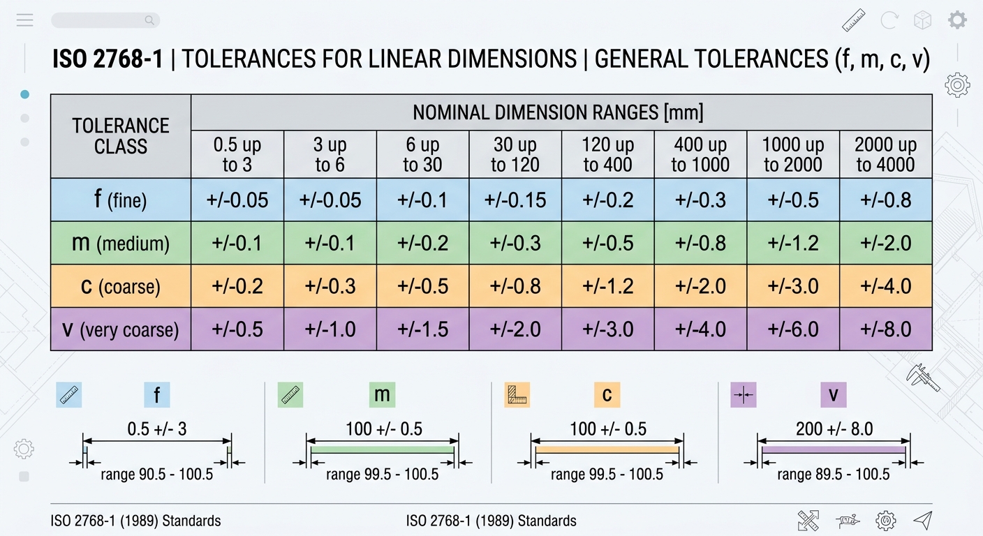
ISO 2768 is a shorthand system. Instead of tolerancing every dimension on a drawing individually, you add one note — something like ‘ISO 2768-mK’ — and every undimensioned linear, angular, and geometric feature inherits a default tolerance based on its nominal size.
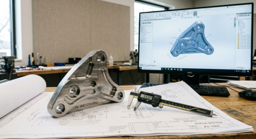
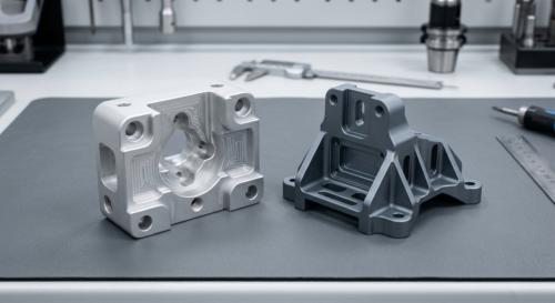
For a typical CNC machined bracket, a mK callout (medium linear, K geometric) is a common default. It’s not a tolerance you specify per feature — it’s a blanket safety net for the dimensions nobody bothered to tolerance individually. Most shops, including CNC machining suppliers, treat ISO 2768-mK as a reasonable baseline unless the drawing says otherwise.
The catch: general tolerances were never designed to control fit between two machined parts. They control ‘this hole is roughly where I drew it,’ not ‘this hole must align within 0.05 mm of a mating pin across a bolt pattern.’
GD&T (Geometric Dimensioning and Tolerancing, per ASME Y14.5 or ISO 1101) controls relationships — not just size. A ±0.1 mm dimension tells you how big a hole is. It says nothing about whether that hole is perpendicular to a mounting face, or whether it’s positioned relative to a datum that another part will register against.
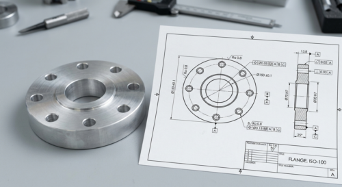
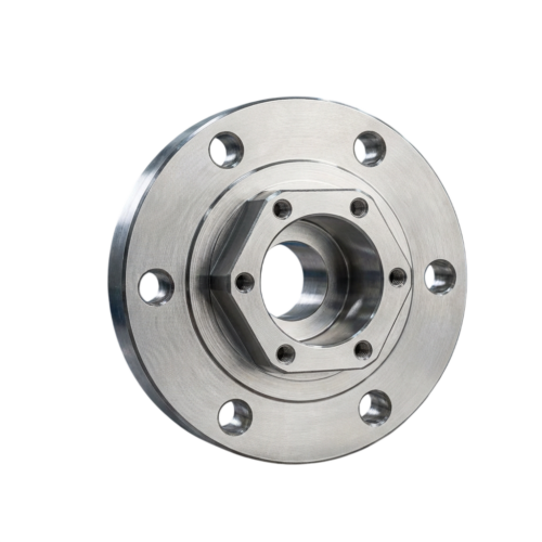
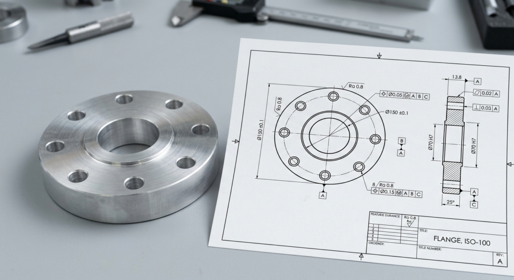
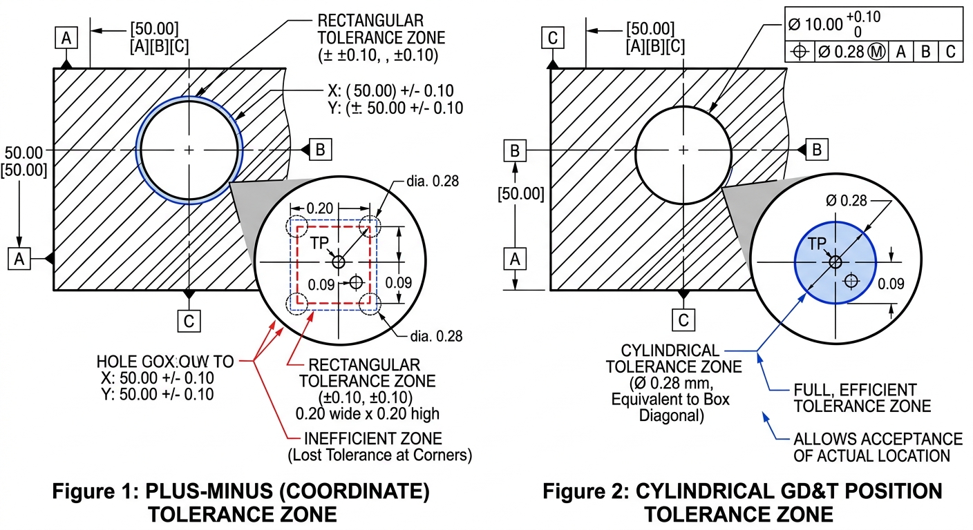
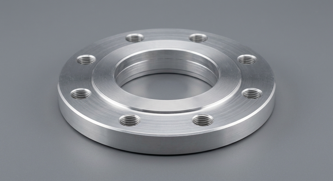
Consider a flange with four bolt holes. ISO 2768 tolerances each hole’s location independently around its nominal position — but doesn’t control how the holes relate to each other or to a bore in the center. Two parts can both be ‘within tolerance’ individually and still fail to bolt together, because the holes drift in opposite directions. A position tolerance with a datum reference frame solves exactly this problem — it ties the hole pattern to a common reference and defines a cylindrical tolerance zone instead of a boxy ± zone, which is both more accurate to how holes actually get inspected and roughly 57% more tolerance area for the same nominal accuracy.
This is why GD&T shows up on virtually every drawing involving fits, seals, bearing interfaces, or robotic and aerospace assemblies — see our related breakdown on why aerospace companies rely on multi-axis machining for how tight geometric control and complex tool paths go hand in hand.
An industrial equipment manufacturer once sent us a flange print with every hole toleranced individually at ±0.05 mm and a general note of ISO 2768-fH for everything else. The parts machined fine and measured within print. But in assembly, roughly one in eight units leaked at the gasket face.
The root cause wasn’t the hole tolerances — it was flatness on the sealing face, which had been left to the general ‘H’ class geometric tolerance. That class allows more flatness deviation than a gasket interface can tolerate under bolt-down pressure. Once the drawing added an explicit flatness callout (a GD&T feature control frame) directly on the sealing face, the leak rate dropped to a level the customer considered acceptable for the application.
The lesson: general tolerances are a default, not a decision. If a feature’s function depends on flatness, perpendicularity, or position, it needs its own callout — the general note is not a substitute for engineering judgment on functionally critical surfaces.
Not every feature deserves a feature control frame. Over-tolerancing a drawing with GD&T on every dimension slows down programming, inflates inspection time, and drives up unit cost for no functional benefit.
For these features, ISO 2768-mK (or fH for tighter general work) is enough. Adding GD&T here just adds cost without improving function — a mistake covered in more depth in our design for CNC machining cost-reduction guide.
Some features simply can’t be trusted to a general tolerance note, because the part’s entire function depends on a geometric relationship, not just a size.
These are the features worth discussing directly with your machining partner before finalizing the drawing — not after first-article inspection reveals a problem. Our guide to setting realistic tolerances walks through how to decide which features deserve this level of control.
A well-prepared drawing almost never uses GD&T exclusively or ISO 2768 exclusively — it layers them. The general note handles everything by default; individual feature control frames override that default only where function demands it.
| Aspect | ISO 2768 General Tolerances | GD&T (ASME Y14.5 / ISO 1101) |
|---|---|---|
| What it controls | Linear/angular dimensions without explicit tolerances | Form, orientation, location, runout, profile |
| Best for | Non-critical features, mounting holes, general stock sizes | Fits, mating parts, assemblies, functional datums |
| Inspection method | Calipers, standard gauges | CMM, optical comparator, functional gauges |
| Cost impact | Low — no extra tooling or inspection | Higher — tighter process control, more inspection time |
| Drawing complexity | One note block, minimal callouts | Feature control frames, datum structure |
| Typical use case | Bracket mounting holes, non-mating edges | Bearing bores, sealing faces, robotic joint interfaces |
| Risk if misapplied | Parts fail to assemble or seal | Unnecessary cost with no functional benefit |
A good rule of thumb: if a feature interfaces with another part, bears a load, rotates, or seals, tolerance it explicitly with GD&T. Everything else can ride on the general note.
Every feature control frame you add has a downstream inspection cost. A position tolerance with a datum reference frame usually requires CMM measurement to verify properly — a manual caliper check won’t tell you if a hole pattern is truly aligned to a datum. That’s fine when the feature is functionally critical. It’s expensive overhead when it isn’t.
This is especially relevant in low-volume and prototype runs, where inspection time is a larger percentage of total part cost than in high-volume production. A prototype housing with GD&T on every hole might need a full CMM report per unit, while the same part under a general tolerance note might pass with a quick manual check. Whether that inspection cost is justified is application-dependent — a medical device bracket may need it regardless of volume, while an internal test fixture usually doesn’t.
If you’re unsure which features on a drawing justify the added inspection cost, it’s worth a conversation before quoting rather than after — our team regularly reviews RFQ drawings through our contact page to flag over- or under-toleranced features before they become a cost surprise.
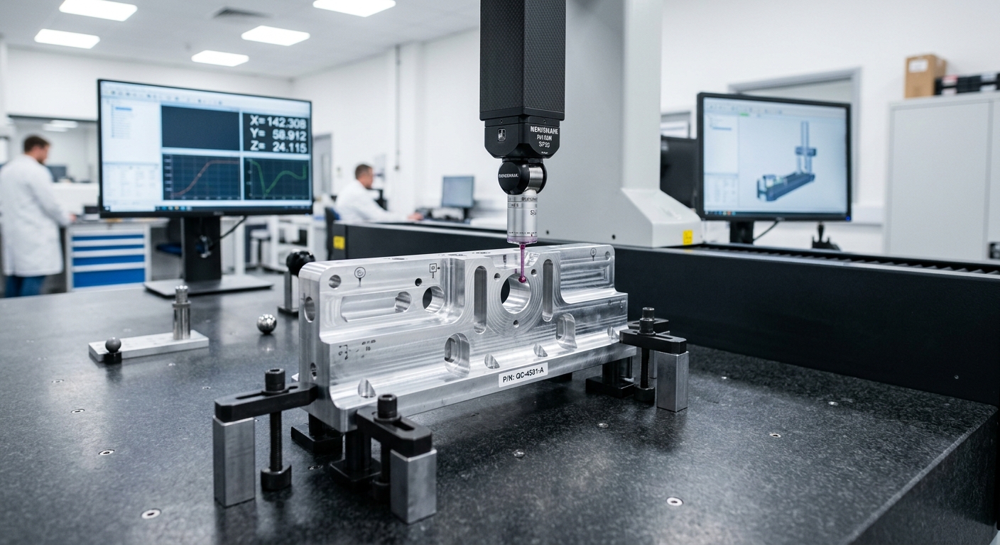
Tolerancing decisions don’t happen in a vacuum — material behavior and process capability influence how tight a callout can realistically be held.
Thin-walled aluminum parts can distort after machining due to residual stress relief, making tight flatness or position callouts harder to hold consistently — see our notes on machinability trade-offs in Aluminum 6061 vs 7075. Stainless steel work-hardens during cutting, which can affect surface finish and dimensional stability on tightly toleranced bores — covered in our stainless steel machining guide.
3-axis milling, turning, and 5-axis machining all have different achievable tolerance ranges depending on setup and fixturing. A feature that needs a tight positional GD&T callout across multiple faces may require a 5-axis setup to hold datum relationships in a single operation, rather than multiple manual re-fixturing steps that introduce stack-up error.
Most GD&T-related rejections trace back to a handful of avoidable drawing errors:
Reviewing these details early — ideally before the print goes out for quotes — prevents the back-and-forth that delays first-article approval and repeat production planning.