 25 Aug, 2026
 Industry News Design & Manufacturing
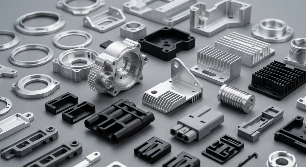
For CNC-machined metal parts, a practical minimum wall thickness is around 0.8 mm for aluminum and 1.0 mm for stainless steel under normal shop conditions, while machined plastics generally need at least 1.0-1.5 mm to avoid warping and chatter. Go thinner than that and you’re not necessarily wrong — but you’re trading reliability for risk, and the risk changes depending on geometry, fixturing, and material behavior, not just a single number on a design chart.
Every design chart on the internet gives you a single number for minimum wall thickness. That number is almost always wrong for your actual part — not because it’s fabricated, but because wall thickness minimums are not a material property. They’re an outcome of geometry, fixturing, tool access, and cutting forces acting together.
A 0.5 mm aluminum wall that’s 5 mm tall and fully supported on three sides machines just fine. The same 0.5 mm wall on a 40 mm tall unsupported boss will deflect under cutting load, chatter, and come out of tolerance — sometimes by 0.05 mm, sometimes by 0.3 mm, depending on tool overhang and spindle speed. Treat published minimums as a starting point for conversation with your machinist, not a design rule you can apply blindly.
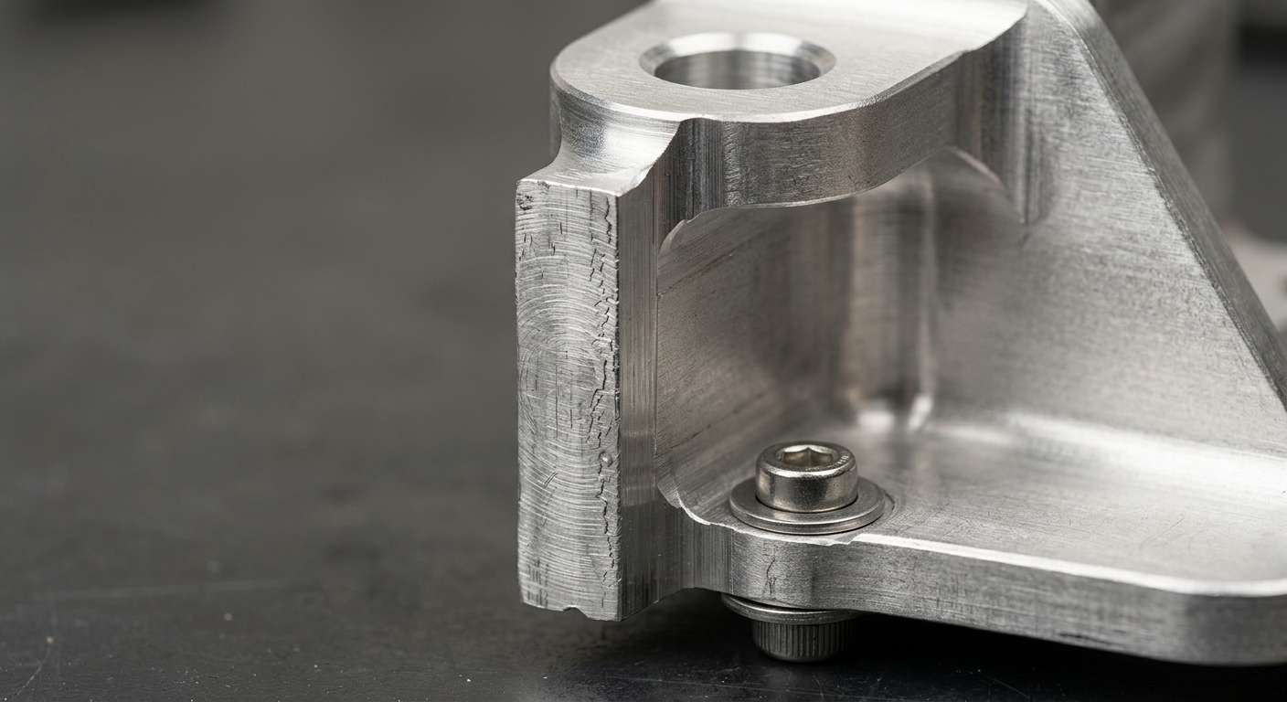
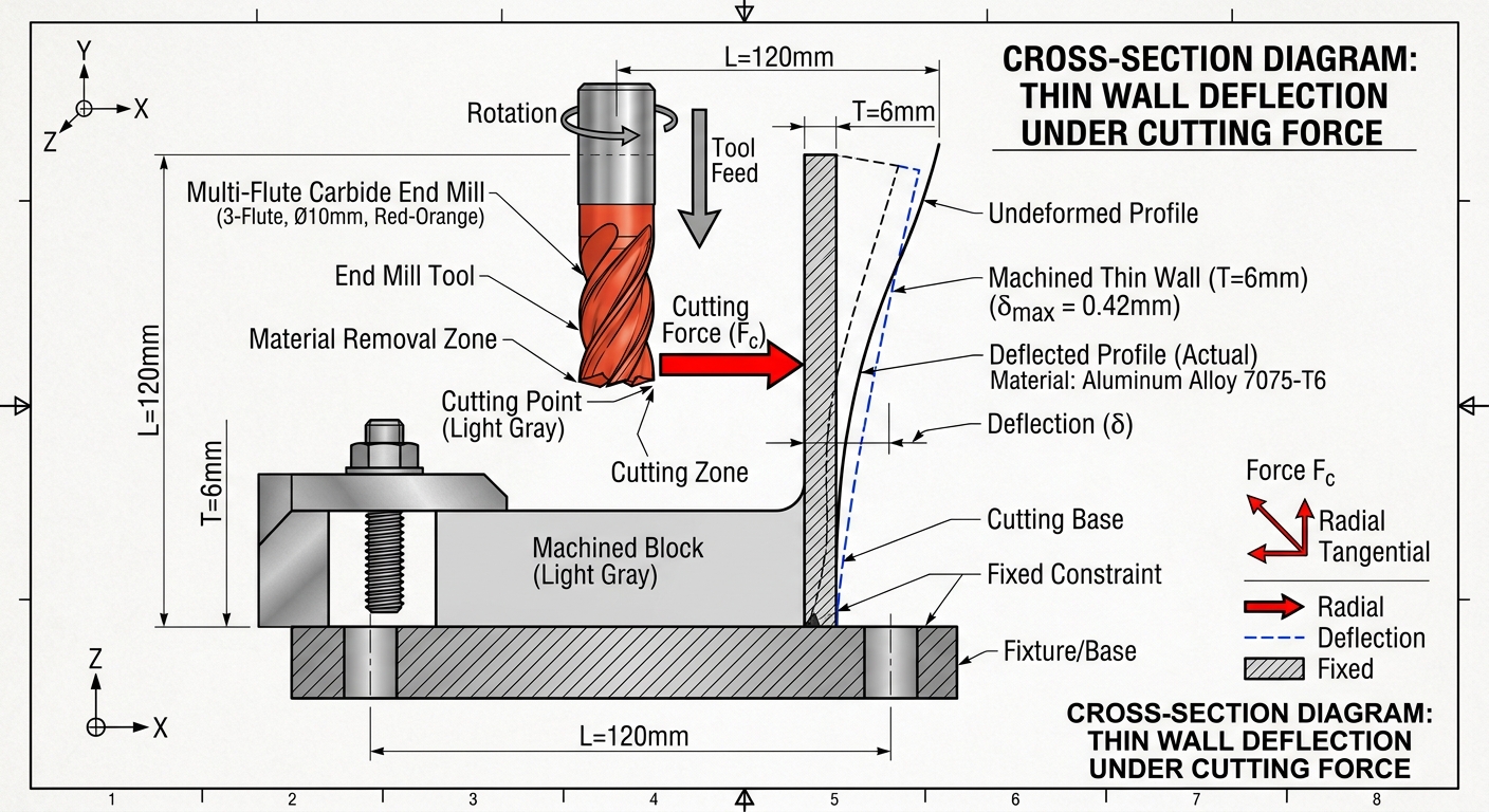
Every milling pass pushes the material sideways before it cuts. A thick wall resists that push; a thin one flexes, then springs back after the tool passes — leaving a wall that’s thicker in the middle than at the ends. This is why thin-wall parts often measure fine at one point and out of tolerance 10 mm away.
Bar stock and plate carry internal stress from rolling or extrusion. Machining away material on one side of a thin wall unlocks that stress, and the wall bows toward the side with less remaining material. This is a major contributor to warping in thin aluminum enclosures and heat sink fins.
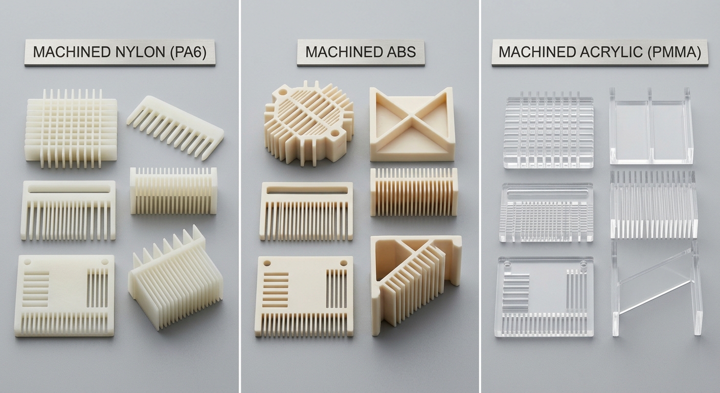
Plastics don’t dissipate cutting heat the way metals do. A thin plastic wall can locally soften, then cool unevenly, causing warp that doesn’t show up until hours after machining. Nylon and ABS are particularly prone to this behavior in thin ribs and standoffs.
Aluminum 6061 is the most forgiving common metal for thin-wall work — it’s machinable at feature thicknesses down to 0.4-0.5 mm in low-stress, well-supported geometries, though 0.8 mm is a safer default for anything load-bearing or with tight flatness requirements. For a deeper look at how 6061 compares to harder alloys like 7075 in machinability and strength, see our breakdown of Aluminum 6061 vs 7075.
Stainless steel behaves differently. It work-hardens as you cut, so thin sections that flex slightly during machining can harden unevenly, leading to inconsistent wall thickness across a batch. We generally recommend 1.0 mm as a practical floor for 304 and 316 in structural walls — our guide to machining stainless steel covers the surface finish tradeoffs that come with thin-wall stainless parts in more detail.
Brass and free-machining alloys cut more cleanly than steel and tolerate thinner sections — down to 0.3 mm in some fixture-supported cases — but thin brass edges are prone to burring, which adds secondary deburring cost that’s easy to underestimate at quoting time.
Plastics fail in thin sections for reasons that have nothing to do with mechanical load. ABS and nylon absorb and release internal heat unevenly during machining, so a rib that measures correctly right off the machine can warp 0.1-0.2 mm over the next 24 hours as it reaches thermal equilibrium. This is why plastic parts with thin standoffs or snap-fit tabs sometimes fail dimensional inspection days after they left the shop floor.
PEEK holds tolerance better than nylon in thin sections because of its lower thermal expansion, but it’s stiffer and more prone to sudden fracture rather than gradual warp — a thin PEEK tab that’s overstressed during fixturing can crack without warning. Acrylic is the least forgiving: thin acrylic edges chip and stress-crack even under light clamping pressure, which is why enclosure windows and light guides in acrylic usually need 1.5 mm minimum unless the design has generous radii.
If you’re choosing between plastic candidates for a thin-wall part, our guide on the best plastics for CNC machining compares dimensional stability across common resins in more depth.
A medical device developer once brought in a nylon housing with 0.7 mm walls around a battery cavity — thinner than our practical floor of 1.2 mm for that material. The first batch machined clean and passed initial inspection. Three days later, on re-measurement, several parts had bowed by 0.15 mm as residual machining heat fully released and the nylon absorbed ambient moisture.
The fix wasn’t a material change. We increased wall thickness to 1.3 mm in the load-bearing sections and added a 0.5 mm radius at the wall-to-base transition, which reduced stress concentration during both machining and post-machining relaxation. The second batch held dimensions within spec through a two-week hold period. This is a common pattern: thin plastic walls often fail on the calendar, not on the machine.
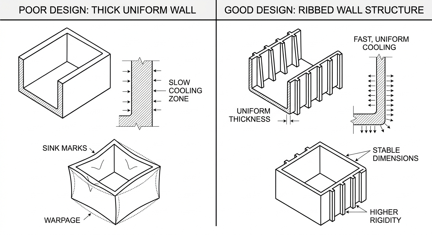
A 0.6 mm wall stiffened by a 1.5 mm rib every 15-20 mm often outperforms a uniform 1.0 mm wall in both stiffness and material cost. Ribs redirect cutting forces into shorter, better-supported spans.
Sharp internal corners concentrate stress and are also where tool deflection is highest, since the cutter has to slow down and change direction. A 0.5-1.0 mm internal radius reduces both machining chatter and long-term stress cracking risk.
Where possible, remove material from both sides of a wall rather than one — this balances residual stress release and reduces one-directional bowing, especially in aluminum plate stock.
A thin wall that can be clamped along its full length machines far more predictably than one held only at the ends. If your design has a wall that will need to float unsupported during a setup, flag it during drawing review rather than after the first article comes back out of tolerance.
Thin-wall parts rarely fail in isolation — they usually fail because a thin section is also carrying a tight tolerance or a cosmetic finish requirement. A ±0.02 mm flatness call on a 0.5 mm aluminum wall is a very different request than the same tolerance on a 3 mm wall, even though the tolerance value is identical. If your drawing specifies tight GD&T on thin features, it’s worth reviewing our guide on how precise your part really needs to be before finalizing wall dimensions, since loosening tolerance on non-critical thin walls can meaningfully reduce scrap rate.
Surface finishing adds another variable: bead blasting or anodizing thin aluminum walls can introduce additional thermal or mechanical stress, occasionally revealing warp that wasn’t visible after machining alone. This is application-dependent, but it’s worth discussing finish requirements for thin sections before committing to a final wall thickness.
Designers often over-correct after one bad experience with thin walls, padding every wall to 3-4 mm out of caution. That solves the warping problem but creates a new one: more material to remove means longer cycle times, more tool wear, and higher machining cost — sometimes 20-30% higher on parts with large removed volumes. The better move is targeted reinforcement (ribs, radii, fixturing changes) rather than blanket thickness increases.
Another frequent mistake is specifying a uniform wall thickness across a part with mixed geometry — thick base, thin sidewalls, thin bosses — without flagging which sections are dimensionally critical. That forces the machinist to either treat every section as high-risk (slower, costlier) or guess which ones actually matter. For general cost-reduction strategies beyond wall thickness, our article on design for CNC machining cost reduction covers related decisions like tolerance zoning and feature count.