 10 Dec, 2025
 Industry News Design & Manufacturing
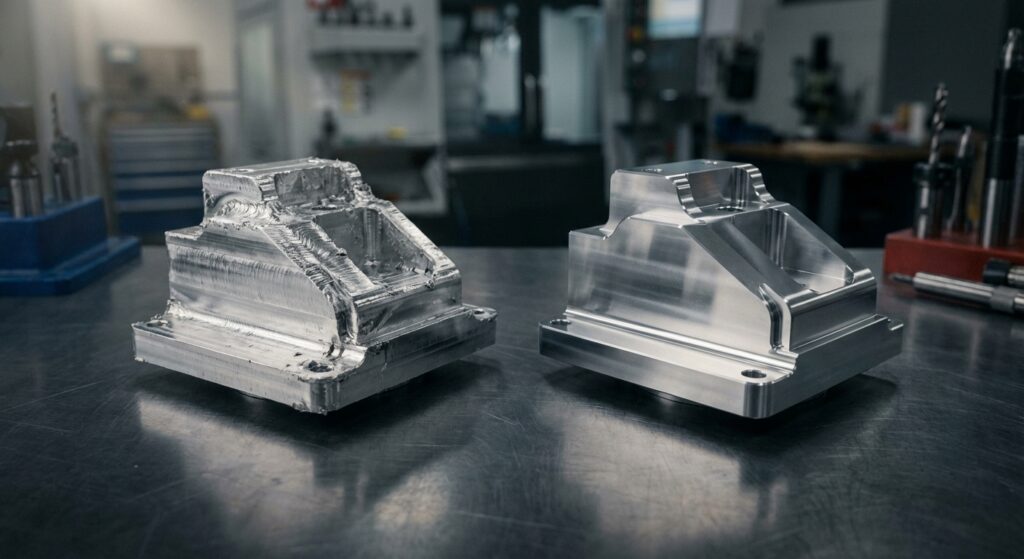
Machining defects are visible or measurable problems that prevent a machined part from meeting its drawing, tolerance, surface finish, or functional requirements. Common machining defects include poor surface finish, dimensional inaccuracies, burrs, chatter, premature tool wear, thermal distortion, and built-up edge.
These problems are usually caused by unsuitable cutting parameters, worn tools, weak workholding, excessive heat, poor chip evacuation, material instability, or unclear inspection requirements. This guide explains how each defect appears, what causes it, and how manufacturers can prevent it during CNC machining.
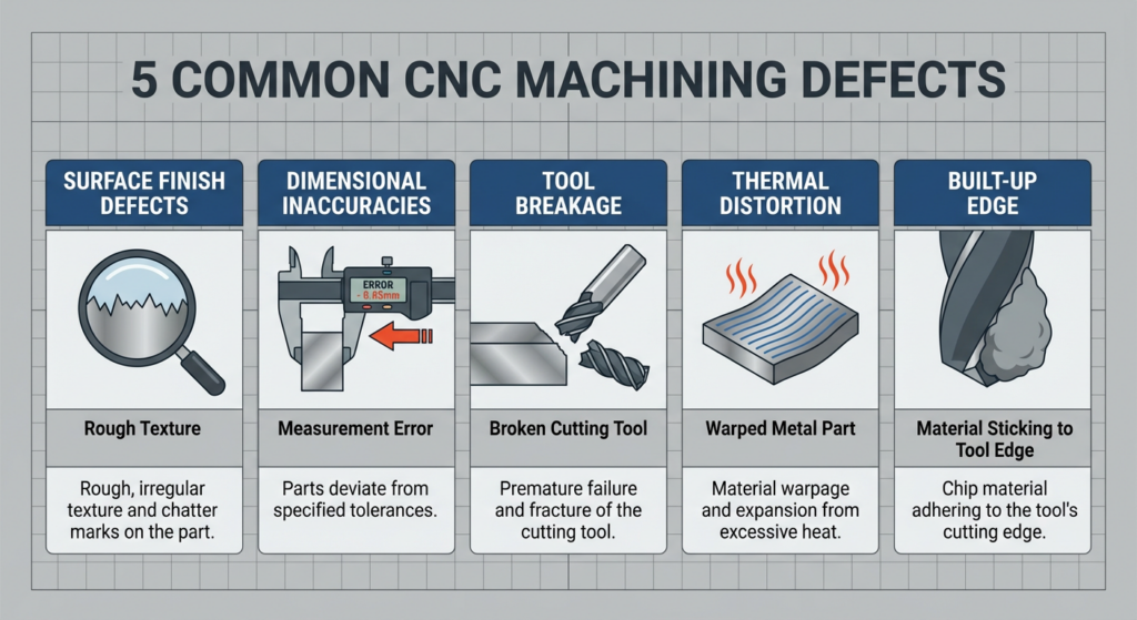
The table below provides a quick comparison of the most common CNC machining defects, their typical symptoms, likely causes, and primary prevention methods.
| Machining Defect | Typical Symptoms | Common Causes | Main Prevention Method |
|---|---|---|---|
| Poor Surface Finish | Rough texture, visible lines, tearing, or inconsistent appearance | Worn tools, unsuitable feeds and speeds, poor chip evacuation, or inadequate coolant delivery | Use sharp tooling, optimize cutting parameters, and improve coolant delivery and chip removal |
| Dimensional Inaccuracy | Features outside tolerance, poor fit, or inconsistent measurements | Thermal growth, tool wear, incorrect offsets, calibration errors, or unstable fixtures | Verify the setup, control temperature, inspect critical dimensions, and manage tool offsets |
| Burrs and Sharp Edges | Raised material around holes, slots, edges, or intersecting features | Dull tools, unsuitable tool exit direction, ductile materials, or incomplete deburring | Optimize toolpaths, use sharp tools, and define edge-break requirements |
| Chatter and Vibration | Repeated wave patterns, abnormal noise, poor surface finish, or shortened tool life | Long tool overhang, weak clamping, unstable cutting conditions, or insufficient rigidity | Increase rigidity, shorten tool reach, and adjust spindle speed, feed rate, or engagement |
| Tool Wear and Breakage | Rapid dimensional drift, damaged surfaces, or sudden tool failure | Excessive cutting load, incorrect tool selection, poor cooling, or chip recutting | Monitor tool life, select suitable geometry, and maintain stable cutting conditions |
| Thermal Distortion | Warping, dimensional movement, or shape changes after cooling | Excessive heat, residual stress, uneven material removal, or excessive clamping | Balance material removal, control heat, and allow stabilization before finishing |
| Built-Up Edge | Material adhered to the cutting edge, rough finish, or dimensional variation | Unsuitable cutting speed, inadequate lubrication, ductile materials, or poor tool condition | Optimize cutting conditions, improve lubrication, and use suitable tool geometry or coatings |
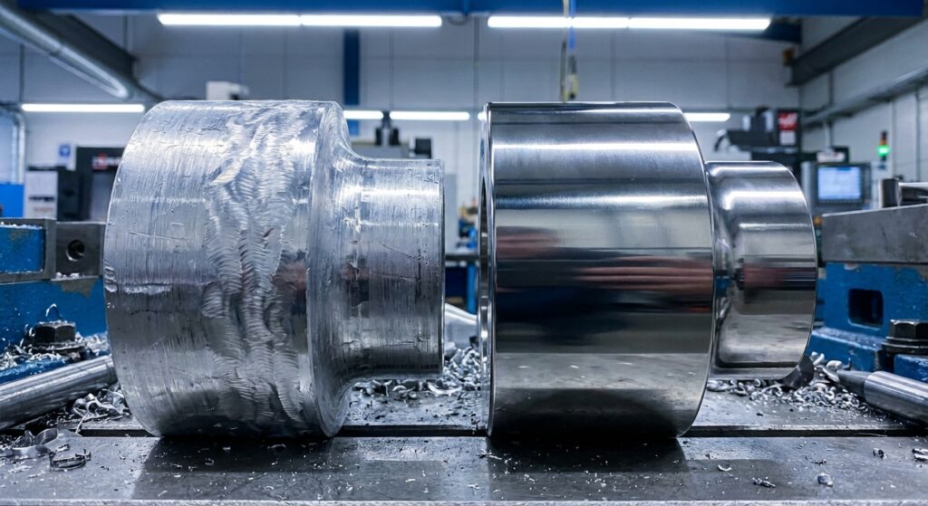
Surface finish defects may appear as rough texture, tearing, scratches, visible feed lines, inconsistent gloss, smeared material, or tool marks. These problems are often the first defects a customer notices, especially on cosmetic, sealing, sliding, or mating surfaces.
A poor finish may also indicate a deeper process problem. Worn tools, unstable cutting, chip recutting, built-up edge, and weak workholding can affect both appearance and dimensional accuracy.
Use the cutting tool manufacturer’s recommended starting values and adjust them according to the material grade, tool diameter, coating, tool engagement, machine rigidity, coolant strategy, and required surface finish. Changes should be evaluated through measured results rather than a single universal speed or feed value.
When machining difficult materials, the correct relationship between cutting speed, feed, chip load, and heat control is especially important. For additional guidance, see our guide to machining stainless steel for better surface quality.
A sharp, stable cutting edge produces a more consistent finish than a tool that has already reached the end of its effective life. Establish tool inspection and replacement intervals using actual tool-life data, spindle load, surface finish trends, and changes in critical dimensions.
Use the shortest practical tool overhang, support the workpiece close to the cutting area, and confirm that the fixture is secure without deforming the part. Machine condition should also be checked when repeated marks remain after reasonable tooling and parameter adjustments.
Coolant or lubricant should reach the cutting zone consistently, while chips should be removed before they can be recut. Monitor coolant concentration, contamination, pH, flow, and cooling performance, and service the system according to the coolant supplier’s guidance and actual operating conditions.
Secondary treatments can change appearance or texture, but they should not be used to hide an unstable cutting process. Review the available surface finishing options only after the underlying machining conditions have been controlled.
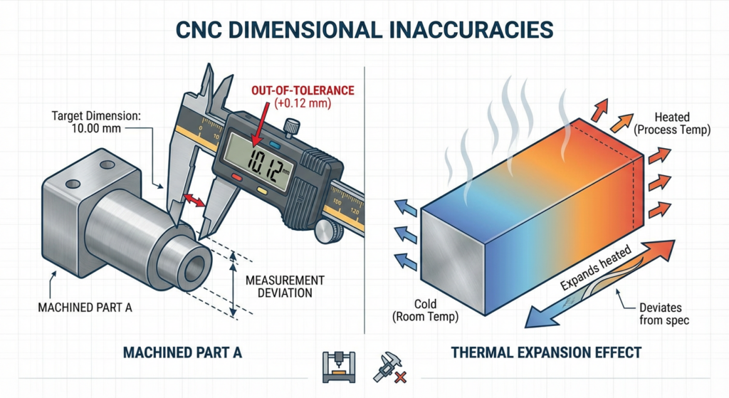
A machined part can appear visually acceptable but still fail because a hole diameter, wall thickness, position, flatness, thread, or overall dimension is outside tolerance. Even a small deviation can prevent assembly, affect sealing, change motion, or create uneven loading in the final product.
Dimensional drift may develop gradually as tools wear and the machine warms, or it may appear immediately because of an incorrect offset, unstable fixture, drawing interpretation error, or measurement problem. The required level of control should match the part’s functional needs, as explained in our guide to machining tolerances and precision requirements.
Confirm the correct drawing revision, program, material, fixture, datums, tooling, and inspection plan before running the batch. Complete a first-piece inspection for critical features instead of assuming that the setup is correct because the program loaded successfully.
Allow the machine and process to reach stable operating conditions before final measurement of high-precision features. The required warm-up and stabilization procedure should be based on the machine, material, part size, tolerance, and production environment rather than a fixed time that is applied to every job.
Use measured in-process data to determine when an offset correction is appropriate. Record significant changes so that repeated drift can be distinguished from a one-time measurement variation or setup mistake.
Critical dimensions should have a defined measuring tool, datum reference, inspection frequency, and acceptance criterion. Measurements taken with different techniques, temperatures, or reference points can create apparent variation even when the machining process has not changed.
Burrs are unwanted projections or raised edges left around holes, slots, milled edges, threads, and intersecting features. They are especially common when machining ductile materials or when a cutting tool exits the workpiece without sufficient support.
Burrs may interfere with assembly, damage mating components, create handling risks, block fluid passages, or prevent a part from meeting its specified edge condition.
Use sharp tools and select cutting geometry suitable for the workpiece material. Toolpaths should be planned so that critical edges remain supported when the tool exits the cut. Where practical, include chamfering or edge-breaking operations directly in the CNC program.
The drawing should specify the required edge condition, such as “break sharp edges,” a defined chamfer, or a maximum allowable burr. Internal intersections and cross holes should be reviewed before production because they may require specialized mechanical, thermal, or manual deburring.
Chatter is a repeating vibration between the cutting tool, machine, fixture, and workpiece. It usually appears as regular waves or marks on the machined surface and may also produce abnormal cutting noise. In addition to reducing surface quality, chatter can accelerate tool wear and create dimensional variation.
Start by improving rigidity. Use the shortest practical tool overhang, support the workpiece close to the cutting area, and confirm that the fixture is secure without deforming the part.
Cutting parameters should then be adjusted to move the operation away from the unstable vibration range. Depending on the tool, material, and machine, this may involve changing spindle speed, feed rate, depth of cut, radial engagement, tool geometry, or toolpath strategy.
A stable finishing pass can improve the final surface after rough material removal, but it will not correct a setup that continues to vibrate. Persistent chatter should trigger a review of the tool, holder, spindle, fixture, and part geometry.
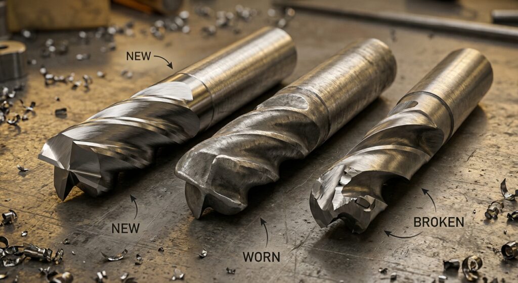
Tool wear can cause gradual dimensional drift, degraded surface finish, higher cutting forces, and longer cycle times. Sudden breakage may damage the workpiece, holder, fixture, or machine and can stop an entire production run.
Typical causes include excessive cutting load, unsuitable tool material or geometry, poor chip evacuation, inadequate coolant delivery, built-up edge, tool runout, unstable entry conditions, and continued use after the cutting edge has reached its effective life.
Tool substrate, coating, flute geometry, edge preparation, and chip space should match the material and operation. A tool designed for aluminum may not perform reliably in stainless steel, while a general-purpose tool may be inefficient in a high-volume, material-specific process.
Avoid sudden changes in engagement and excessive load at corners, entries, or interrupted cuts. Smoother toolpaths and consistent chip formation reduce shock loading and make tool life easier to predict.
Direct coolant or air appropriately toward the cutting zone and prevent chips from being trapped or recut. The best method depends on the material, tool, operation, machine, and whether coolant is permitted for the application.
Track tool performance by material, machine, toolpath, and operation. Use dimensional trends, surface condition, spindle load, cycle count, and visual inspection to define replacement intervals before tool failure affects the batch.
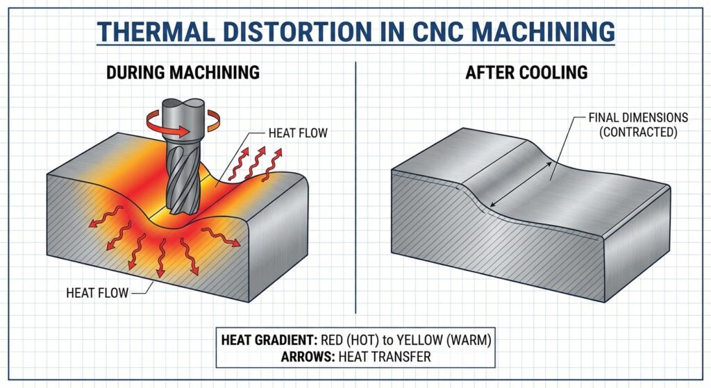
Heat is generated at the cutting zone and transferred through the tool, chips, workpiece, fixture, and machine. As components warm, they expand. When the part later cools or is released from the fixture, dimensions and geometry may change.
Distortion is more likely in thin walls, large flat parts, long shafts, asymmetric components, and materials with significant residual stress. Uneven stock removal or excessive clamping can release or introduce stress even when the cutting temperature appears controlled.
Remove material in a balanced sequence where possible, especially on thin or symmetrical parts. Roughing both sides before final finishing can reduce the risk that one-sided material removal causes the workpiece to move.
Use suitable tooling and cutting parameters to produce stable chips without unnecessary rubbing. More heat is not always solved by simply lowering spindle speed; the complete relationship between speed, feed, engagement, edge condition, and coolant strategy must be evaluated.
For high-precision work, allow the part to return to a stable condition before final finishing or inspection. The required stabilization method should be selected according to the material, part geometry, tolerance, and production process.
A fixture must hold the workpiece securely without forcing it into a temporary shape. Use appropriate support points, soft jaws, distributed clamping, or custom fixtures for parts that are easily distorted.
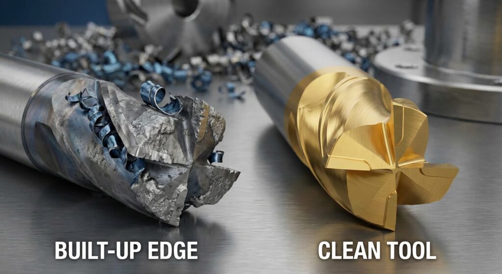
Built-up edge, often abbreviated as BUE, occurs when workpiece material adheres to the cutting edge. As the deposit grows, it changes the effective tool geometry and can produce rough surfaces, dimensional variation, unstable cutting forces, and premature tool damage.
BUE is more likely when machining ductile materials, particularly when the cutting conditions, tool geometry, lubrication, or chip evacuation encourage material adhesion.
Built-up edge becomes more likely when the cutting speed is unsuitable for the specific material and tool combination. Confirm any speed or feed adjustment against the tooling supplier’s recommendations and monitor the resulting surface finish, chip form, cutting load, and tool condition.
Use a coolant or lubricant strategy that reduces friction and helps prevent material from adhering to the cutting edge. Maintain the correct concentration and delivery method where coolant is used, and prevent chips from remaining in contact with the tool.
Polished flutes, sharp cutting edges, material-specific geometry, and appropriate coatings can reduce adhesion. The correct choice depends on the workpiece material, operation, and whether heat or lubricity is the dominant concern.
Regular visual inspection can identify early material buildup before it causes a noticeable defect. When BUE appears repeatedly, investigate the full cutting process rather than relying only on a final light pass to hide the resulting marks.
Machining defect prevention should begin before the first part enters production. A complete manufacturing package allows the supplier to identify tolerance, workholding, tooling, inspection, and finishing risks during the design for CNC machining review.
Buyers and engineers should provide:
Thin walls, deep pockets, long shafts, large flat surfaces, intersecting holes, and features requiring long tool reach should be reviewed before production. Early DFM adjustments can reduce vibration, distortion, burr formation, excessive setup changes, and inspection disagreements.
Different machining defects require different inspection methods. Dimensional features may be verified with calibrated measuring tools, gauges, or coordinate measurement equipment, while surface defects require visual inspection and, where specified, roughness measurement. First-piece and in-process checks help identify drift before an entire batch is completed.
| Defect Type | Common Inspection Method | What the Inspection Confirms |
|---|---|---|
| Dimensional inaccuracies | Calipers, micrometers, height gauges, pin gauges, thread gauges, or coordinate measurement | Size, position, form, fit, and tolerance compliance |
| Surface finish defects | Visual inspection, comparison samples, or surface roughness measurement | Texture, tool marks, scratches, tearing, and specified roughness |
| Burrs and sharp edges | Visual, magnified, tactile, or functional inspection | Edge condition, safe handling, passage clearance, and assembly readiness |
| Warping and distortion | Surface plate, indicator, profile measurement, or coordinate measurement | Flatness, straightness, profile, and shape stability |
| Tool-wear-related drift | First-piece inspection, in-process sampling, and dimensional trend monitoring | Whether dimensions or surface quality change during the run |
| Hole and thread defects | Pin gauges, plug gauges, thread gauges, or functional assembly checks | Diameter, thread form, depth, alignment, and mating performance |
Inspection requirements should be agreed upon before production, especially for critical dimensions, cosmetic surfaces, threads, sealing areas, and assembly interfaces. The equipment, sampling frequency, reporting format, and acceptance criteria should reflect the actual risk and specification.
Review recent scrap, rework, inspection, and customer feedback records. Identify which machining defects occur most often, which machines or operations are involved, and whether the same symptoms appear repeatedly. Photographs and measured examples make later root-cause analysis more useful.
Document the approved program revision, setup method, tooling, workholding, cutting parameters, coolant strategy, inspection method, and tool-life expectation for recurring jobs. Standards should be based on verified process results and updated when the material, machine, geometry, or tooling changes.
Team members should understand how a visible symptom connects to possible causes. For example, regular waves may indicate chatter, gradual dimensional movement may indicate tool wear or thermal growth, and smeared material may indicate built-up edge.
Track defects by job, material, machine, tool, and operation. When a defect appears, verify the root cause before changing several variables at once. Controlled adjustments make it easier to confirm which action actually improved the process.
Common machining defects include poor surface finish, dimensional inaccuracies, burrs, chatter, tool wear or breakage, thermal distortion, and built-up edge. Other possible problems include thread defects, misaligned holes, cracks, dents, and incomplete features.
Machining defects are commonly caused by worn tools, unsuitable cutting parameters, weak workholding, machine-condition problems, excessive heat, poor chip evacuation, material instability, programming errors, or unclear drawing and inspection requirements.
Verify the setup and tool offsets, control thermal conditions, use stable fixtures, monitor tool wear, inspect the first part, and measure critical dimensions at an appropriate frequency during production.
Chatter develops when vibration occurs between the tool, workpiece, fixture, and machine. Long tool overhang, weak clamping, thin unsupported features, insufficient rigidity, and unstable cutting parameters are common causes.
Surface finishing may reduce minor visible marks or change appearance, but it cannot reliably correct dimensional errors, deep chatter, warping, cracks, or other structural problems. The underlying machining process should be corrected first.
Detection methods include visual inspection, dimensional measurement, surface roughness testing, gauges, first-piece inspection, in-process checks, and functional assembly testing. The selected method should match the drawing requirement and the function of the feature.
Machining defects are rarely caused by a single factor. Surface finish problems, dimensional inaccuracies, burrs, chatter, tool wear, thermal distortion, and built-up edge usually result from a combination of tooling, cutting parameters, workholding, material behavior, heat, and inspection control.
Preventing these problems requires early DFM review, stable machining processes, suitable tooling, clear drawing requirements, and appropriate inspection. If you are developing a precision CNC machined part, submit your drawing and material requirements to Ruo Chen for manufacturability and production review.