 15 Apr, 2026
 Industry News Material Guide
Most PEEK machining failures come down to heat and stress management, not tool selection. PEEK has a glass transition temperature around 143°C and a melt point near 343°C — nowhere near steel, but plenty low enough for a dull tool or a high feed rate to soften the surface, smear material, and leave you with a part that measures fine at 10am and is out of tolerance by 2pm because it’s still relaxing. Get the thermal and stress side right, and PEEK actually machines beautifully. Get it wrong, and you’ll burn through material fast wondering why a $200/kg polymer keeps ending up in the scrap bin.
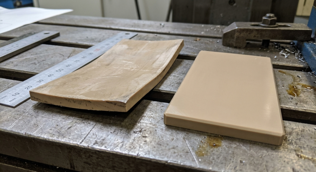
Here’s the frustrating part: the machining looks perfect, dimensions check out on the CMM, and then two days later the part has bowed 0.15mm across a 100mm span. That’s not a fluke — it’s internal stress finally winning.
PEEK stock, especially extruded rod and plate, carries residual stress from how it was cooled during manufacturing. When you machine away material asymmetrically — say, milling a pocket on one face only — you unlock that stress and the part moves to find a new equilibrium. It can take hours or days to fully settle.
Don’t try to hit final tolerance in one pass. Rough machine leaving 0.5-1mm of stock on critical surfaces, let the part sit for 12-24 hours (or run a stress-relief bake at around 200°C for annealed-grade PEEK), then finish machine. It adds a day to your lead time. It also saves you from shipping parts that fail inspection at the customer’s dock.
If your tolerances are tight, this is exactly the kind of stack-up problem worth reading about in Understanding Tolerances: How Precise Does Your Part Really Need to Be? before you finalize a drawing.
PEEK doesn’t chip away like aluminum — it can gum up, smear, and re-solidify onto your cutting edge if you generate too much localized heat. That shiny, slightly discolored surface finish you sometimes see on PEEK parts? That’s a sign the tool was rubbing, not cutting.
Because PEEK is a poor thermal conductor compared to metals, heat doesn’t dissipate into the bulk material — it stays concentrated right at the cutting edge. A dull insert or a feed rate that’s too slow (yes, too slow, not too fast) means the tool dwells in one spot too long and cooks the surface.
A medical device shop we’ve talked to had this exact issue on a batch of PEEK spinal implant blanks — discolored bores traced back to a worn 6mm end mill that nobody had checked in three shifts. Swapping tooling on a schedule, not just when it visibly fails, fixed it.
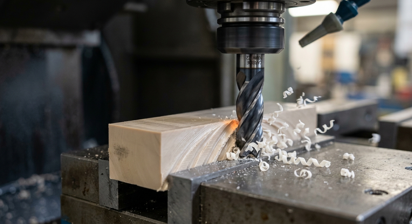
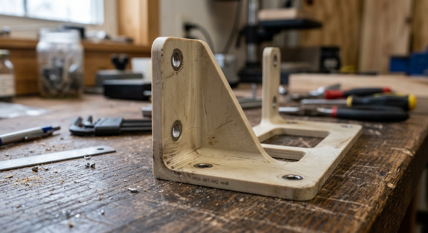
PEEK is tougher than most engineering plastics, but it’s not infinitely forgiving. Thin walls under 1mm, sharp internal corners, and unsupported bosses are where PEEK parts crack or chip during machining — usually right at the moment you think you’re almost done.
The problem is almost always excessive cutting force on a feature that has nowhere to flex. Unlike a metal part that might just deflect slightly, thin PEEK sections can snap cleanly if the tool pushes too hard on one side.
If you’re designing the part, avoid internal corners sharper than a 0.5mm radius where possible — this is one of the same principles covered in Design for CNC Machining: 10 Tips to Reduce Cost, and it applies just as much to plastics as metals. On the machining side, reduce depth of cut near thin sections, use climb milling to pull the tool away from unsupported edges instead of pushing into them, and add wax or low-melt fixturing to support thin walls during the cut.
PEEK isn’t as moisture-sensitive as nylon, but it does have a relatively high coefficient of thermal expansion — roughly 47 µm/m°C, several times higher than steel. That means a part measured warm off the spindle can shrink measurably once it cools to room temperature.
This catches people off guard on tight-tolerance bores and press-fit features. A hole drilled while the part is at 40°C from cutting friction might read 0.02-0.03mm smaller once it settles at 20°C — enough to turn a good fit into an interference fit that won’t assemble.
Let parts cool to ambient temperature before final inspection, ideally in the same room where they’ll be measured. For critical bores, peck drill in stages with air cooling between passes rather than one continuous plunge, and finish-bore as a separate operation after the part has had time to stabilize.
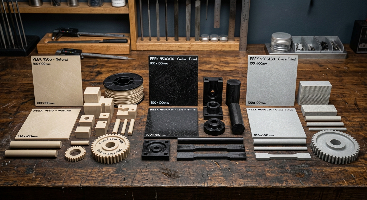
Not all PEEK is created equal, and a lot of machining headaches actually start at the material selection stage. Unfilled virgin PEEK machines cleanly but has lower stiffness and wear resistance. Carbon-fiber-filled PEEK is stiffer and more dimensionally stable — but the fibers are abrasive and will chew through standard carbide tooling fast.
Glass-filled and bearing-grade (PTFE/graphite-filled) PEEK each bring their own quirks: glass fiber is even harder on tooling, while PTFE-filled grades can smear more easily under heat.
If your part needs maximum dimensional stability for a tight-tolerance aerospace fitting, carbon-filled PEEK is often worth the extra tooling wear. If it’s a low-load insulator, unfilled PEEK will machine faster and cheaper. This decision matters more than most people realize — it’s covered in more general terms in The Best Plastics for CNC Machining: Strength, Stability, and Cost, but for PEEK specifically, always confirm the fiber content with your supplier before quoting tooling costs.
PEEK parts often end up in sealing applications — semiconductor wafer carriers, valve seats, downhole tool components — where surface finish isn’t cosmetic, it’s functional. A finish that looks fine to the eye at 3.2 Ra can still leak if there are micro-tears from a tool that was dragging instead of cutting.
The telltale sign is a slightly fibrous or torn appearance under magnification, rather than a clean sheared surface. This usually means the feed rate was too low relative to spindle speed, letting the tool push material aside rather than shearing it cleanly.
Increase feed slightly, keep the tool sharp, and consider a light finishing pass with a fresh insert dedicated only to final surfaces — don’t use the same tool that roughed the part. For critical sealing faces, a secondary polish or lapping step after machining is common practice, similar to how finishing decisions are made on metal parts, which we cover in Surface Finishing.
Sometimes the material behaves fine and the real issue is how it’s held. PEEK’s flexibility relative to metal means standard vise clamping can distort a thin part just enough to throw off flatness once it’s released — even though everything measured perfectly while still clamped.
This is a subtle failure mode because it doesn’t show up until after the part comes off the fixture, which means it’s easy to blame the wrong step in the process.
Use vacuum fixturing or multiple low-pressure clamping points instead of one or two high-pressure ones. For complex geometries, a soft jaw custom-machined to the part’s shape distributes force evenly and avoids the point-loading that causes distortion. This is one more reason experienced shops treat PEEK jobs differently from aluminum jobs from the very first setup, not just at the toolpath stage.