 10 Apr, 2026
 Industry News Design & Manufacturing
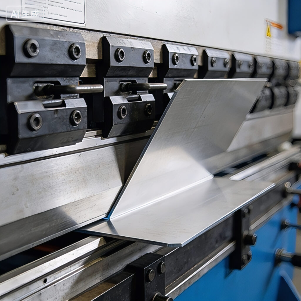
Bend radius is the inside curve of a sheet metal bend, and K-factor is the ratio that tells you where the metal’s neutral axis sits inside that bend — together they determine exactly how much flat material you need before forming. Get either one wrong and your flat pattern won’t match the finished part, which means holes land in the wrong place and assemblies don’t fit. Most fabrication headaches trace back to designers picking a bend radius that ignores tooling reality, or software using a generic K-factor instead of one matched to the actual material and thickness.
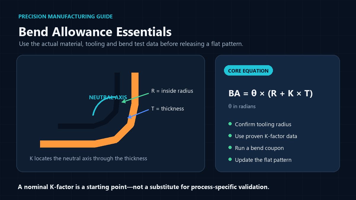
Here’s a mistake we see constantly: designers specify a sharp, near-zero bend radius because it looks cleaner in the CAD model. In practice, a truly sharp bend doesn’t exist in sheet metal — the material will crack, thin out, or spring back unpredictably if you force it too tight.
The bend radius is measured on the inside of the bend, and it’s driven largely by the punch tool radius used in the press brake. A general rule of thumb: minimum bend radius should equal the material thickness for most steels and aluminum alloys, and go up to 1.5x thickness for stainless steel because it work-hardens faster and resists deformation.
Go tighter than that minimum and you risk visible cracking on the outer surface, especially with harder alloys or thicker gauges. This is one of the classic common machining defects that shows up when tolerances and material behavior aren’t considered together at the design stage.
K-factor is simply a ratio between 0 and 1 that locates the neutral axis — the layer inside the bent metal that neither stretches nor compresses — relative to the material thickness. A K-factor of 0.5 means the neutral axis sits exactly in the middle. A K-factor of 0.33 means it sits closer to the inside of the bend.
Why does this matter so much? Because the neutral axis length is what determines your flat pattern size. Every bend calculator, whether it’s SolidWorks Sheet Metal, Fusion 360, or a manual formula, needs this number to convert a 3D bent part back into an accurate 2D flat blank.
Softer, more ductile materials like aluminum tend toward higher K-factors (0.40–0.45) because the neutral axis shifts toward the center under less resistance. Harder materials like stainless steel skew lower (0.33–0.40) because the inside surface compresses less relative to the outside stretch.
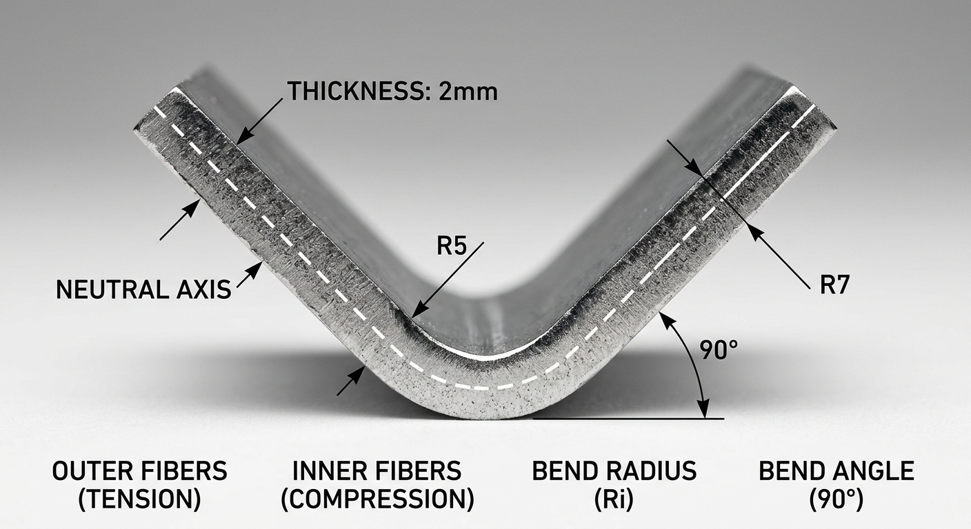
The standard formula is: Bend Allowance = Angle (in radians) x (Radius + K-factor x Thickness). This tells you exactly how much material length is consumed by the bend itself, which you then add to your flat leg lengths to get the correct flat pattern.
For example, take a 90-degree bend in 0.060-inch aluminum with a 0.060-inch inside radius and a K-factor of 0.44. Plug in the numbers: 1.5708 x (0.060 + 0.44 x 0.060) = 1.5708 x 0.0864 = 0.1357 inches. That’s your bend allowance — the exact amount of material the bend uses up.
Skip this calculation, or use a default K-factor your CAD software assumed without verifying, and your finished part can be off by several hundredths of an inch across multiple bends. On a multi-bend enclosure, those errors stack fast.
Thicker material doesn’t just need a bigger minimum bend radius — it also shifts the K-factor itself. Thinner sheets (under 0.5mm) behave almost elastically through the bend, pushing the neutral axis closer to center and the K-factor higher. Thick plate, especially anything over 3mm, compresses more on the inside and the K-factor drops.
This is why a single K-factor value across your whole product line is a rookie mistake. A fabricator producing both a thin aluminum bezel and a thick steel bracket in the same run needs two different K-factor assumptions, or the flat patterns for one of them will be wrong.
If your parts span a wide range of thicknesses or materials, it’s worth reviewing our materials resource before finalizing a design — matching K-factor assumptions to the actual alloy and gauge avoids costly rework.
A customer building an outdoor equipment enclosure specified a 0.5mm inside bend radius on 2mm stainless steel panels — well below the 1.5x thickness minimum stainless steel needs. The first batch came back with visible micro-cracking along every bend line, invisible until the powder coat was applied and the stress lines showed through.
The fix wasn’t complicated: bump the radius to 3mm (1.5x the 2mm thickness) and re-run the flat pattern with a corrected K-factor of 0.38 instead of the default 0.5 the design software had assumed. The redesigned parts formed cleanly, and the flat pattern dimensions shifted by almost 4mm across the largest bend — enough to have thrown off every mounting hole if it hadn’t been caught before production.
This kind of issue is exactly why bend radius and K-factor deserve the same attention you’d give to tolerance decisions elsewhere in the design.
Even with a perfect K-factor and bend allowance calculation, the final bend angle rarely matches the tool angle exactly. Metal springs back slightly after the press brake releases it — typically 1 to 4 degrees depending on material and thickness.
Stainless steel springs back the most, often needing an over-bend of 3–5 degrees to land on a true 90-degree angle. Aluminum is more forgiving, usually 1–2 degrees. Experienced shops compensate for this with tooling angle adjustments or a second hit pass, but it’s worth flagging on your drawing if the angle tolerance is tight.
Designers who ignore springback often blame the K-factor when a part comes back slightly open — but the two are separate issues. K-factor gets your flat pattern length right; springback compensation gets your final angle right.
If you’re still finalizing part geometry, our guide on reducing design cost covers related principles that carry over well into sheet metal work, even though it’s framed around machining.