 28 Apr, 2026
 Industry News Machining Basics
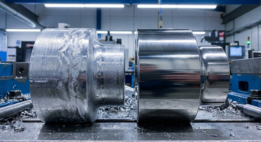
Surface roughness is not a cosmetic number. It changes how a part seals, slides, carries lubricant, bonds, reflects light and resists fatigue. Two machined surfaces can look similar and even share the same Ra value while behaving differently in service. The safest drawing therefore connects the surface requirement to function, names the measurement system and gives the supplier enough information to inspect the same thing you intended.
A measured profile contains several scales of geometric variation. Form is the broad shape of the part. Waviness is the longer-spaced undulation that can come from machine motion, vibration or distortion. Roughness is the shorter-wavelength texture left by cutting, grinding, polishing or another manufacturing process. Lay describes the dominant direction of that texture.
This distinction matters because the instrument separates these components with filters and cutoff settings. Change the cutoff and the reported roughness value can change even though the physical surface has not. ASME B46.1 defines surface texture and its constituents—including roughness, waviness and lay—while ISO 21920-1:2021 defines rules for indicating profile surface texture in technical product documentation. Your drawing and inspection plan should identify the standard that governs the requirement rather than assuming every system calculates and reports parameters identically.
Ra is the arithmetic average of the absolute profile-height deviations from the mean line over the evaluation length. In practical terms, it summarizes the average vertical texture into one stable number. That makes Ra useful for general process control, comparing batches and setting a broad finish target for many machined surfaces.
Ra is also forgiving. A single deep scratch or tall isolated peak may have limited influence on the average when most of the profile is smooth. That is why a part can meet an Ra requirement and still leak across a gasket line, damage a soft seal or initiate wear at a local defect. Ra is not wrong; it simply answers an average-height question.
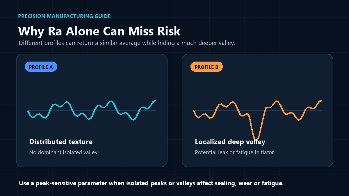
Rz is a peak-sensitive roughness height parameter based on peak-to-valley information within the measured profile. It gives more weight to prominent local highs and lows than Ra does. This can make it useful when isolated valleys or peaks influence sealing, fatigue, coating performance or contact stress.
The exact Rz calculation and notation depend on the referenced standard and instrument configuration. Do not write only “Rz 6.3” and assume every supplier will interpret it the same way. Name the governing standard, units, filtering and evaluation method. If one extreme defect is the real concern, discuss whether a maximum-height or defect-specific requirement is more appropriate than relying on Rz alone.
| Question | Ra | Rz |
|---|---|---|
| What does it emphasize? | Average absolute profile deviation | Peak-to-valley behavior within the evaluated profile |
| Useful for | General finish and process consistency | Peak-sensitive functional risk |
| Can miss | An isolated deep valley or tall peak | Spacing, lay and the full shape of the texture |
| Drawing need | Parameter, value, units, standard, filtering/cutoff and inspection agreement | |
A surface profilometer does not simply trace a line and report an unquestionable number. The result depends on the stylus or sensor, evaluation length, short- and long-wavelength filtering, sampling strategy and measurement direction. ASME’s B46.1 guidance specifically shows that changing filter cutoff changes what is classified as roughness versus waviness and can change the reported Ra value.
Measure across the lay when the goal is to capture the dominant machining marks, unless the drawing or functional analysis requires another direction. Make sure the feature is long and accessible enough for the chosen cutoff and evaluation length. On a narrow sealing land, a standard trace may not physically fit; the designer and supplier should agree on an alternative before production.
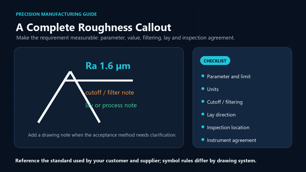
A complete surface requirement normally needs more than a roughness value beside a symbol. State the parameter and limit, including units. Reference the drawing system or standard. Add the cutoff or filtering requirement when it is functionally important. Show lay direction when directional texture affects sealing, sliding or appearance. Identify the surface or zone to be inspected, and add a note for the inspection method when access or sampling could cause disagreement.
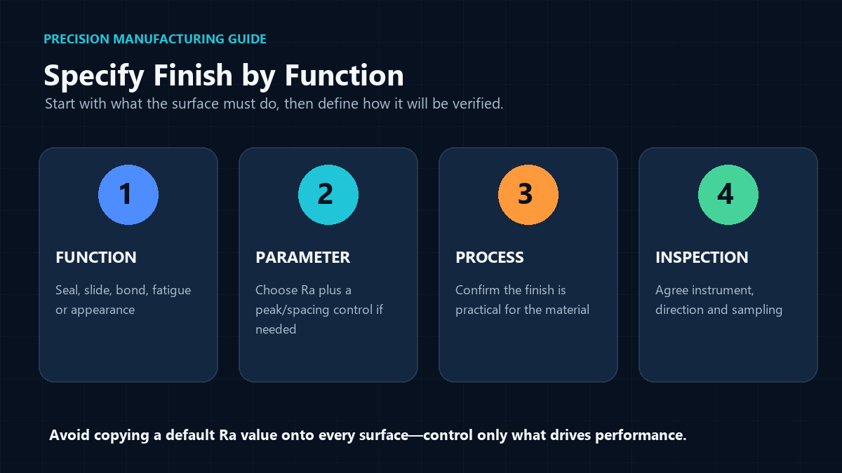
Avoid applying one tight finish value to every face. Finishing every nonfunctional surface to a low Ra can add polishing, grinding, slower feeds, tool changes and inspection time without improving the part. Control the sealing land, bearing seat, optical face or fatigue-critical transition that actually drives performance, then leave ordinary clearance or cosmetic surfaces at a practical process finish.
Start with the failure mode. A static cosmetic cover mainly needs a consistent appearance. A sliding guide needs controlled friction and wear. A lubricated bearing surface may need texture that retains lubricant rather than the lowest possible Ra. A gasket land needs a texture and lay that do not create a leakage path. A bonded surface may need enough texture for adhesion but not contamination or sharp defects.
There is no universal “best” roughness value for these cases. Material, coating, contact pressure, seal type, speed, lubricant, mating surface and manufacturing process all matter. Use prototype testing or application standards for safety-critical decisions, and review the requirement with the manufacturer before the drawing is released.
Contact stylus instruments remain common because they provide traceable profile measurements on accessible surfaces. Optical methods can help with soft materials, very small features or broader three-dimensional texture, but they may not correlate directly with a stylus result. The drawing should not switch casually between methods when acceptance depends on a tight limit.
Inspection should also control basic technique: clean the surface without altering it, orient the trace correctly, avoid edges and obvious damage unless defects are part of the requirement, and take enough traces to represent the functional zone. If the part has several equivalent sealing lands or cavities, define a sampling plan rather than allowing one convenient location to represent the entire lot.
Surface texture works best when design, manufacturing and inspection use the same definition. Review it together with the dimensional requirements in our guide to machining tolerances, explore available surface finishing options, or see our CNC machining capabilities. If you have a sealing land, bearing seat or cosmetic face that needs a controlled finish, send the drawing through our contact page so the callout and inspection method can be reviewed before quoting.